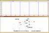
I'm a relative newbie to LTSpice and have been simulating a circuit using multiple data-latches of the 4013 type. Frustratingly, I couldn't get it to do what I wanted, so I tried a simpler simulation with just one latch to try and spot the error.
The relevant latch model that LTSpice offers is the 'dflop'.
I grounded the dflop D input and clocked the clock pin, expecting to see the Q output at 0. But no, Q = 1. Eh? What's going on? After much gnashing of teeth I discovered that by connecting the D input to a 0V voltage-generator instead of to ground, the dflop behaved as expected and gave me Q = 0.
I recall reading in the 'Help' for gate elements that LTSpice makes a distinction (for reasons best known to itself) between 0V and ground in connection with some inputs, but I couldn't see any reference to this in relation to the dflop. Indeed, I couldn't find any help at all for the dflop element!
A real 'gotcha' for newbies.
")
