Hello there,
I had been mentioning a way to get rid of the LM358 crossover distortion for years and there's even an app note floating around on the web somewhere. We started talking about this again and some pic's posted showed some nasty crossover distortion so i decided to test it first hand.
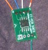
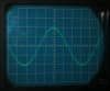
The board picture shows the board itself, minus the resistors used., while the scope picture shows the output waveform at 10kHz, amplitude 2v peak. Any slight distortion at the peak is caused by the frequency generator which uses a non linear technique which is not perfect, so the output wave looks just like the input wave. The gain is set up to be a voltage follower with output connected to the inverting input. The non inverting input has a 10k series resistor to protect the input stage if the power becomes disconnected for any reason, as the wave generator puts out it s own voltage signal.
As you can see from the scope pic, there is no noticeable crossover distortion. This happens with no load as well as any load going to the most negative supply, and i used a 1k resistor as the load for this test. The most negative supply is considered to be the ground reference, and the wave generator is set to have a suitable offset voltage so it can go plus and minus around that level on the input of the op amp.
The wave looks extremely clean near the zero crossing (and i zoomed in too at one point to check) and this is because the output has the resistor to ground.
Note the actual device used was an LM432 SMD package, but according to the old National data sheet it's the same amplifier as the LM358.
I had been mentioning a way to get rid of the LM358 crossover distortion for years and there's even an app note floating around on the web somewhere. We started talking about this again and some pic's posted showed some nasty crossover distortion so i decided to test it first hand.
The board picture shows the board itself, minus the resistors used., while the scope picture shows the output waveform at 10kHz, amplitude 2v peak. Any slight distortion at the peak is caused by the frequency generator which uses a non linear technique which is not perfect, so the output wave looks just like the input wave. The gain is set up to be a voltage follower with output connected to the inverting input. The non inverting input has a 10k series resistor to protect the input stage if the power becomes disconnected for any reason, as the wave generator puts out it s own voltage signal.
As you can see from the scope pic, there is no noticeable crossover distortion. This happens with no load as well as any load going to the most negative supply, and i used a 1k resistor as the load for this test. The most negative supply is considered to be the ground reference, and the wave generator is set to have a suitable offset voltage so it can go plus and minus around that level on the input of the op amp.
The wave looks extremely clean near the zero crossing (and i zoomed in too at one point to check) and this is because the output has the resistor to ground.
Note the actual device used was an LM432 SMD package, but according to the old National data sheet it's the same amplifier as the LM358.
")
