Electro Tech is an online community (with over 170,000 members) who enjoy talking about and building electronic circuits, projects and gadgets. To participate you need to register. Registration is free. Click here to register now.
Welcome to our site! Electro Tech is an online community (with over 170,000 members) who enjoy talking about and building electronic circuits, projects and gadgets. To participate you need to register. Registration is free. Click here to register now.
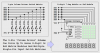
There's been a lot of people wanting scrolling LED message systems, so I've added a tutorial about using a PIC to drive a matrix of 64 LED's - so far there's two sections to it, with more to come.
A couple of points/questions:
- Do you use a 150 ohm resistor for each row pin and none for the col pins? I think that's how you've done it but the text wasn't clear on that point.
- Doesn't the brightness of each LED in a row depend on the number of LEDs lit? The current through the row pin is limited to 20mA - with all LEDs in the row lit, each would see 2.5mA. But if only one was lit, it would see 20 mA. Using a row driver and moving the resistors to the col pins could mitigate this with no change to the code.
- It would be great to see a tutorial on a lower pin count version of this. maybe using power shift regs (like the TPIC6B595 or similar) but that's probably a somewhat different subject.
A couple of points/questions:
- Do you use a 150 ohm resistor for each row pin and none for the col pins? I think that's how you've done it but the text wasn't clear on that point.
- Doesn't the brightness of each LED in a row depend on the number of LEDs lit? The current through the row pin is limited to 20mA - with all LEDs in the row lit, each would see 2.5mA. But if only one was lit, it would see 20 mA. Using a row driver and moving the resistors to the col pins could mitigate this with no change to the code.
It's already like that, each LED receives about 2.5mA, regardless of how many are lit - it doesn't matter which side the resistors go, as long as the software is written accordingly. As it stands, the resistors feed the columns, and the rows are switched by the multiplexing.
I'm hoping to have time to record some video clips of the display in action this weekend, but it depends how busy things get!.
But I thought I'd get the tutorial out there now, as it's useful as it is.
- It would be great to see a tutorial on a lower pin count version of this. maybe using power shift regs (like the TPIC6B595 or similar) but that's probably a somewhat different subject.
It's already like that, each LED receives about 2.5mA, regardless of how many are lit - it doesn't matter which side the resistors go, as long as the software is written accordingly. As it stands, the resistors feed the columns, and the rows are switched by the multiplexing.
ok, now I'm confused. if the resistors are 150 and only one is lit in a row, won't the row pin see 13.3 mA (assuming 4V with Vcc of 5 and a Vf of 2V, exact number may be different). secondly, when all 8 in the row are lit, each column with a 150 resistor, wont the current through the row pin sum up to 8*13.3 unless it has a resistor in series?
As it stands it's designed to be as simple hardware as possible, it's hard enough work wiring 64 LED's anyway!
ok, now I'm confused. if the resistors are 150 and only one is lit in a row, won't the row pin see 13.3 mA (assuming 4V with Vcc of 5 and a Vf of 2V, exact number may be different). secondly, when all 8 in the row are lit, each column with a 150 resistor, wont the current through the row pin sum up to 8*13.3 unless it has a resistor in series?
Bear in mind though that current figure suggested is a short term pulse, the average will be 1/8th of it.
Each resistor only feeds a single LED at any one instant, which keeps their brightness constant.
I just (this second - while in mid message) tried measuring the current taken from the 9V battery. With the numeric scrolling program (13.2 - which happens to still be in the PIC) the maximum reading I got was 31.5mA from the battery.
ok, but your instaneous peak will be 8X. if it's really 13.333 mA per, that makes for 107 mA when the entire row is lit. turn on all LEDS and that's 107 continuous through the PIC, minus a bit for the blanking between row selects. I'd be a bit wary of that boundary case and would put some drivers on the rows.
That looks like another nice tutorial. May I make a suggestion?
I think you could improve display brightness significantly at minimal cost or trouble while maintaining that 'simple' tutorial value.
The pin "sink" spec limits your row driver pins to 25-ma no matter how many column LEDs are turned on. Consider adding a 160-ma NPN driver to each row pin to utilize the full 20-ma "source" capability of your column pins.
Better yet, scan common anode rows with 200-ma PNP drivers and take advantage of the 25-ma sinking capability of each column pin.
I think that's what I said. Nigel's point is that the duty cycle average is < the pin limit even if the instantaneous current is well above it. Note that he has no current limiting resistors on the rows. I would think > 100 mA pulse is risky and would design in drivers, though.
I think that's what I said. Nigel's point is that the duty cycle average is < the pin limit even if the instantaneous current is well above it. Note that he has no current limiting resistors on the rows. I would think > 100 mA pulse is risky and would design in drivers, though.
Nigel is getting the low current readings because of the "limiting" effect of the I/O pin current specs'. The total current for one through eight lighted column LEDs would be limited by the 25-ma "sink" current spec' of the row driver pin.
Good brightness can be had with as little as 5-ma to 10-ma average current for each LED. This requires 40-ma to 80-ma peak current for a 12.5% duty cycle and a row driver that can sink 320-ma to 640-ma.
Given the "keep it simple" nature of Nigel's tutorial, his hardware / software solution is appropriate and provides adaquate brightness and a foundation of understanding that could help many newcomers.
A couple of points/questions:
- Do you use a 150 ohm resistor for each row pin and none for the col pins? I think that's how you've done it but the text wasn't clear on that point.
- Doesn't the brightness of each LED in a row depend on the number of LEDs lit? The current through the row pin is limited to 20mA - with all LEDs in the row lit, each would see 2.5mA. But if only one was lit, it would see 20 mA. Using a row driver and moving the resistors to the col pins could mitigate this with no change to the code.
I believe he's using the current limiting resistors on the column pins and 'scanning' rows so he has the current limiting resistors in the correct place.
I think we agree NPN or N-channel MOSFET row drivers would improve brightness.
- It would be great to see a tutorial on a lower pin count version of this. maybe using power shift regs (like the TPIC6B595 or similar) but that's probably a somewhat different subject.
I agree but I think that's beyond the scope of Nigel's "keep it simple" strategy.
I do have a couple 'cool' designs of my own and just recently received some TPIC6B595 samples but I lack the time and patience to put together any kind of a tutorial.
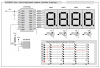
If you're interested in something like the 9-pin example below which supports up to 7 modules (either 8x8 LED matrix or 8-digit 7-segment displays), let me know and I'd be happy to pass along the driver source code. Each module uses a single driver IC, 8 column driver transistors, and provides PWM brightness control from super-bright to black.
How does the PIC output pin limit the current? I've not seen or heard of this. There is nothing in the port block diagrams to indicate this. It just shows 2 mosfets. I've blown pins before and assumed it was due to over current.
1 just got some dual color 8x8 common cathode led matrix's and some STP16C596 16-Bit, constant current LED sink driver chips and some uln2803a my problem is how to wire all this together to a 18f2550 or a 18f4550.Nigels tutorial will help a lot with the code part but I'am a little unsure how to hook up these chips to the matrix.eventually i want to tie about 10 of them together to form a moving message and a keypad+usb to input new messages but that's later first I just need one to experiment with.I've attached a partially finnished schematic and was wondering if somebody could look at it and tell me how I'am doing so far and point out any mistakes or inprovements or tell me if it will work at all.I choose the STP16C596 thinking I could cut down on chip's and resistors needed compared to using 74hc595's for shift registers.
I think you could improve display brightness significantly at minimal cost or trouble while maintaining that 'simple' tutorial value.
The pin "sink" spec limits your row driver pins to 25-ma no matter how many column LEDs are turned on. Consider adding a 160-ma NPN driver to each row pin to utilize the full 20-ma "source" capability of your column pins.
Better yet, scan common anode rows with 200-ma PNP drivers and take advantage of the 25-ma sinking capability of each column pin.
My original plan was to use source and sink drivers in order to push more current through the LED's - and the original circuit I started drawing incorporated that - but I thought it was getting a little away from the 'simple' philosophy of the tutorials.
While doing mental calculations of suitable resistor values I realised it's quite plausible using just the PIC to drive the displays, so I dropped the drivers and increased the values of the current limiting resistors to 150 ohms.
Due to the modular nature of my tutorials, a further thought was to optionally add driver boards between the PIC and the display - I was thinking of two seperate boards, a 'sink' board and a 'source' board - both of which could also be used for other purposes (again reinforcing the modular nature of the boards).
BTW, I've just assembled a quick program that puts all the LED's ON, and measured the battery current - it was only 62mA? - which seems rather low?, but the LED's seem plenty bright enough. This was on my meter at work, I wonder is the current ranges aren't reading properly? - it very rarely gets used on current, I'll measure again with my meter at home.
As for LED brightness, the scrolling numbers tutorial is clearly visible across the full length of the workshop - about 40 feet.
I agree that there is no need that i can see to blank the display before updating it , did you see what it looked like without blanking it ?
maybe its worth a try?
nice tutorial
I agree that there is no need that i can see to blank the display before updating it , did you see what it looked like without blanking it ?
maybe its worth a try?
I agree. There is nothing wrong with your design considering the scope of your tutorial. My Charlieplexed display experiments showed you could get 'decent' brightness by directly driving the displays.
But I did discover a significant increase in brightness by simply adding a column or row driver transistor (which ever way you're scanning) and thought I'd pass along that observation.
The four transistors in the circuit below really make a big difference (sorry about the fuzzy picture).
Mike
<added>
I should also mention that there are some very low current (3-ma/segment) 7-segment displays from Fairchild and Agilent that provide very good brightness levels when directly driven in a multiplexed design. I wonder if there are "low current" discrete LEDs available for your 8x8 matrix?
1 just got some dual color 8x8 common cathode led matrix's and some STP16C596 16-Bit, constant current LED sink driver chips and some uln2803a my problem is how to wire all this together to a 18f2550 or a 18f4550.
I believe you're going to need "source" drivers for the LED anodes. The STP16C596 and the ULN2803A are both "sink" drivers.
If you can exchange your matrix displays for common anode versions then you could use the STP16C596 16-bit "sink" driver for the LED cathodes along with a UDN2981A "source" driver (instead of the ULN2803A) to drive the common anodes.
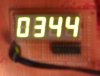
Quick update - I've added a short video clip of the scrolling display in action, about 20 seconds worth. Interestingly you get a nice interaction between the LED strobing and the camera, which gives a 'twinkling' effect to the LED's.
BTW, if anyone is interested?, I 'stole' the bit patterns from the Hitachi type LCD modules - I'm currently doing the letters as well.
This site uses cookies to help personalise content, tailor your experience and to keep you logged in if you register.
By continuing to use this site, you are consenting to our use of cookies.

")