Electro Tech is an online community (with over 170,000 members) who enjoy talking about and building electronic circuits, projects and gadgets. To participate you need to register. Registration is free. Click here to register now.
Welcome to our site! Electro Tech is an online community (with over 170,000 members) who enjoy talking about and building electronic circuits, projects and gadgets. To participate you need to register. Registration is free. Click here to register now.
I think you are basically correct. Without additional startup circuitry, either noise or built in delays due to the physical structure (or both) will determine the initial state.
The propagation delays are not identical for both gates. One will win. Components are not identical, but the propagation delay, I think is the biggest factor. It's actually a way of doing simulations. If you time slice, little balls, so to speak as they go through each gate, but allow say 5 time slices, you get the next state, but you cannot have anything change instantaneously.
Not only latches can be powered up in a 'indeterminate' state, many other devices such as counters have the same problem.
A device in common use is the 4017 counter/decoder, many wannabes assume that the counter will initialise at the start count and omit the required power up Reset circuit, which will cause their circuits to malfunction.
A simple rule I apply is, if a logic IC has a Reset Pin use it, add a power up circuit , dont just connect it high or low.
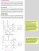
A)to get inverted outputs you just need to invert at each output,
hint: doing the math first, you may find a simpler solution...
B)same as a, technically a decoder decodes only how the matrix is setup, the Boolean is the logic behind it, if you change the Boolean so it fits your new model, then adjust the circuit to the Boolean it will work appropriately.
using the Boolean you can then simplify the equations thus cutting down to minimum logic required
This depends on whether or not you are allowed to use pull downs instead of pull ups. Right now the first circuit has all pull ups, but if you change them to pull downs then you can change the N type FETs to P type FETs and invert the input logic (change A1 to A1' and A0 to A0' and vice versa).
Did you try that?
In some cases you may not be allowed to use pull downs because it is often a requirement that the output impedance for the 0 state has to be lower than the output impedance for the 1 state.
Obviously adding output inverters will slow down the decoder so that is usually undesirable.
This site uses cookies to help personalise content, tailor your experience and to keep you logged in if you register.
By continuing to use this site, you are consenting to our use of cookies.