MatheusLPS
New Member
Hello people.
I am designing an power inverter.
My idea is transform 12VDC in 120VAC@60Hz.
I will make a signal PWM at 25Khz comparing a triangle wave and a sini wave. OK.
But, to make things simpler in the beginning, I am testing with an static root wave at 25Khz provided by a 555 IC.
I threw this signal on a IR2481 gate driver to switch my two IRFP460 mosfets.
So I started with a basic circuit:
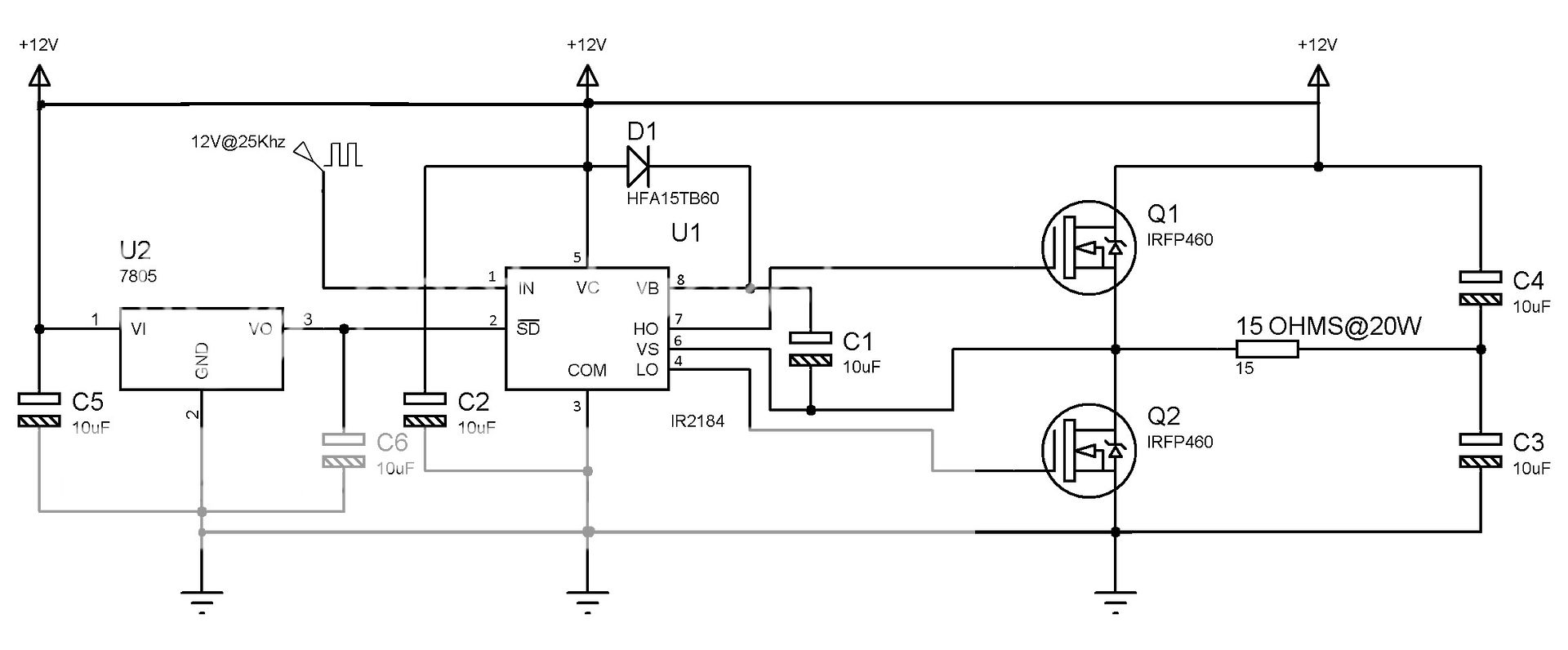
This one is working very well. I am using a single power supply with 12VDC. Look the all the power lines and grounds are the same.
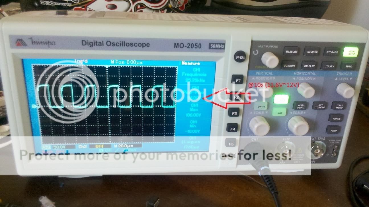
The signal at my gate is ~12V. Nice:
And measuring the voltage across the resistor I came with this:
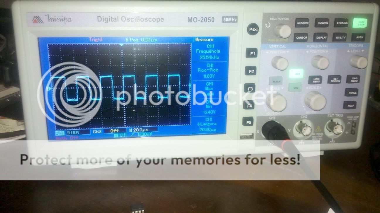
12Vp.p. It looks that is working. .
.
BUT.....
Lets say that I need to work with to separated power supply. One will be my power supply for the control circuit (12V).
Lets consider that I will use another power supply with 12VDC to power the mosfets and capacitors....
So now I have to power that has different ground lines......
My problem is the COM PIN of the IR2184. Accordingly to the datasheet, I need to connect it to the ground of the "HIGH" power supply. When I say "HIGH" I am referring to the power supply that feeds the mosfets.
In this example, the power supply is 12V, but it can be 24V, 100VDC..... I do not know yet.....
I connect the COM PIN to there and what happened? My IR2184's burned... twice........
What is the correct way to connect the two power supply's and my control circuit?
bye
I am designing an power inverter.
My idea is transform 12VDC in 120VAC@60Hz.
I will make a signal PWM at 25Khz comparing a triangle wave and a sini wave. OK.
But, to make things simpler in the beginning, I am testing with an static root wave at 25Khz provided by a 555 IC.
I threw this signal on a IR2481 gate driver to switch my two IRFP460 mosfets.
So I started with a basic circuit:
This one is working very well. I am using a single power supply with 12VDC. Look the all the power lines and grounds are the same.
The signal at my gate is ~12V. Nice:
And measuring the voltage across the resistor I came with this:
12Vp.p. It looks that is working.
.BUT.....
Lets say that I need to work with to separated power supply. One will be my power supply for the control circuit (12V).
Lets consider that I will use another power supply with 12VDC to power the mosfets and capacitors....
So now I have to power that has different ground lines......
My problem is the COM PIN of the IR2184. Accordingly to the datasheet, I need to connect it to the ground of the "HIGH" power supply. When I say "HIGH" I am referring to the power supply that feeds the mosfets.
In this example, the power supply is 12V, but it can be 24V, 100VDC..... I do not know yet.....
I connect the COM PIN to there and what happened? My IR2184's burned... twice........
What is the correct way to connect the two power supply's and my control circuit?
bye
Last edited by a moderator:
