Electro Tech is an online community (with over 170,000 members) who enjoy talking about and building electronic circuits, projects and gadgets. To participate you need to register. Registration is free. Click here to register now.
Welcome to our site! Electro Tech is an online community (with over 170,000 members) who enjoy talking about and building electronic circuits, projects and gadgets. To participate you need to register. Registration is free. Click here to register now.
it is possible to make inductance measurements with a PC sound card. The software sends an audio signal and monitors the level thru the component. I have software from Elektor(late 90's) and I see a similar project in this months EPE Everyday Practical Electronics. I suppose it just depends on the accuracy and range required which solution suits.
PC sound card,allready LC meter, ebay, nothing of that.. to mi all these opcion aren't avaliable to me... I live in venezuela... and here the electronic word ir very small...
Electrical parts: US$11.00
Perf circuit board: find scrap or buy US$15.00
small box: scrounge one for free and adapt
wire, battery, terminals: US$6.00
This assumes you have a soldering iron and a VOM.
As a hobbyist, you should become skilled at finding free hardware and parts by stripping old equipment that others are throwing away, like old televisions, radios, computers and other such things.
well i have to buy the programmer of PIC, download the sofware, do the printed board, etc... a million of things.. but thanks to all for your help.. any dude i will come to this forum..
I tracked down the Elektor project, the parts are 5 resistors 1R,10R,100R,1K,10K and 2 switches a DPDT and a 5 position rotary. I have the software. The measurement range claimed 50uH to 10H and 100pF to 100,000uF and will display input/output impedences of filters. The big problem is that it is a DOS program written by a mathematician Dr Olfsmann and I haven't tried it with XP. I don't know if the Dr is still with us.
I tracked down the Elektor project, the parts are 5 resistors 1R,10R,100R,1K,10K and 2 switches a DPDT and a 5 position rotary. I have the software. The measurement range claimed 50uH to 10H and 100pF to 100,000uF and will display input/output impedences of filters
Hai Anthony123,
Better you try with PIC based project indicated below. https://electronics-diy.com/lc_meter.php
It appears really GOOD. you need not Know much. only you have to one tome arrange to programm the PIC and wire the rest like any other project. the designer claims Good accutacy.
Perhaps some one near you can be of help in getting the chip loaded with the HEX file provided by the designer.
well i have some questions:
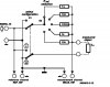
What's it the funcion of J2 and J3??
if a have the hex code what i have to do later??
PD: my neirbors don't know anything about electronic.. and in my city nothing know about programing PIC's
SW1 - Zero out the readings.
SW2 - Capacitance / Inductance switch.
J3 - turns on the backlight on LCD displays that have LED backlight.
J1 - used by 16x2 two line character LCD displays.
J2 - displays the initial frequency of the LM311 oscillator which should be around 550KHz.
If you want to have a quick go, **broken link removed** a really simple programmer you can breadboard to put your PIC in.
For starter projects, it's probably best to use the circuit designer's code, so that you aren't troubleshooting the circuit AND your programming at the same time. I'm sure other members can put up some programming resources.
Simple as it looks- Thanks to you and Mark Feldman, the designer.
Few doubts! where is Vpp? evem if it is derived from com port who will take care of high voltages on (higher then Vdd on other pins and higher on MClr pin?
i feel it becomesa risk to apply port pins without any protection.
This site uses cookies to help personalise content, tailor your experience and to keep you logged in if you register.
By continuing to use this site, you are consenting to our use of cookies.