Continue to Site

Welcome to our site!

Electro Tech is an online community (with over 170,000 members) who enjoy talking about and building electronic circuits, projects and gadgets. To participate you need to register. Registration is free. Click here to register now.

  • Welcome to our site! Electro Tech is an online community (with over 170,000 members) who enjoy talking about and building electronic circuits, projects and gadgets. To participate you need to register. Registration is free. Click here to register now.

IF U CAN SOLVE THIS.... UR DAMN GOOD!!!!

Status
Not open for further replies.

cyprio7

New Member
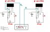
please note that for simplification iv only drawn 2 "sensor things" which provide two outputs D0 and D1 in this diagram, however in the real circuit there are 8, and which range from D0 to D7.

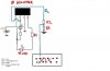
ok heres the purpose of this circuit. threre is an IR transmitter and IR modulated reciever, which drives the IR transmitter. I am using this circuit on a robot to detect objects that the robot may collide into..... i therfore, bounce the IR signal off a wall for example, then it is recieved at the receiever.

When the IR signal is recieved by the reciever, the reciever gives out a "**LOW**" output at its Pin.2. When it ISNT recieving the IR signal it is giving out a *HIGH* at Pin 2.


The normal LED which is circled in green, lights up when pin 2 is low, this is because pin 2 is low, but the other end is 12V, therefore current flows and the LED lights up. When pin2 gives out a high, i.e 12V, because the other end is 12V and ther is no potential difference, no current flows, therefore, the LED doesnt light up.


Now, when i dont connect Pin2...... i.e the wires D0 and D1 to the PIC, this circuit works PERFECTLY. When nothing is detected, Pin 2 gives out a HIGH and the LED isnt on.. and if it detects something, Pin2 goes low and the LED comes on.

The problem..... As SOON as i connect D0 and D1 to the PIC, or emulation board the problem starts. When nothing is detected, all LEDs are off, however, if ONE reciever detects something, and it makes the LED light up, EVERY single LED lights up, not just that one!

Does anybody know what could be causing this problem?? remember, when i dont connect D0 and D1 to the pic, the sensors and LEDs work perfectly and light up when they are supposed to.

any help would be REALLY appreciated... im going mad over this

thanks
 

Attachments

  • circuit_194.jpg
    circuit_194.jpg
    43 KB · Views: 913
..

there's nothing wrong with the PIC....also....the software is perfect... this is why im so baffed
 
Lets see the software! .... Are the PIC fuses and ports configured correctly?? Which device is it?
 
Re: ..

cyprio7 said:
there's nothing wrong with the PIC....also....the software is perfect... this is why im so baffed

I will trust Hardware over software anyday.
 
Re: ..

Styx said:
cyprio7 said:
there's nothing wrong with the PIC....also....the software is perfect... this is why im so baffed

I will trust Hardware over software anyday.

I agree with that!... "the software is perfect" LOL... That is yet to be determined.
 
wrong wiring!!

Your connections are wrong.
1. pin 2 can 'never' be low, according to your wiring.
2. The IR receiver would have burnt out by now.
3. The PIC will also burn out, if it is'nt already.

The pin 2 is connected to +12v via R and LED. This means a constant 12v-1.8 =10.2v is available at pin 2. the same 10.2 v is connected to the PIC. This 10v will play havoc with the various ICs.
Please check the Data sheets of the IRRX and rewire, with all new components. The present components may be french fried by now :!: :!:

ps: What is the IRRX IC ?
Try TSOP1738 for good sensivity and direct interface to the PIC. Less complicated and has 3Pins +, - and o/p. @38khz oscillator.
 
Re: wrong wiring!!

docel said:
The pin 2 is connected to +12v via R and LED. This means a constant 12v-1.8 =10.2v is available at pin 2. the same 10.2 v is connected to the PIC. This 10v will play havoc with the various ICs.

That's a good point... you can't drive a 10v logic signal directly to the input of a PIC that is running at 5v or so... it's going to trip the internal protection circuitry (such as ESD protection diodes) and I wouldn't be the least bit surprised if it behaved oddly, or if it died completely :lol:

I think your title is grossly overstated... something like "if you can solve this, you are at least a competent beginner with electronics and PICs" would be more appropriate, this isn't rocket science :roll:
 
Re: wrong wiring!!

docel said:
Your connections are wrong.

His IR receiver wiring is correct and is working. He told us that.

docel said:
1. pin 2 can 'never' be low, according to your wiring.

In fact, it can because green LED lit up. Why not?

docel said:
2. The IR receiver would have burnt out by now.

The only way the IR receiver would have burnt out is PIC driving current into pin2. But as pin2 is connected to PIC input pins, this cannot happen.

docel said:
3. The PIC will also burn out, if it is'nt already.

Yes, there is 10.2V to the PIC but this is current limited by the LED and series resistor. The excess voltage /current is fed to the PIC input pins which do have protection diodes connected to the supply rails.

So I would say 99% the PIC is still not damaged. Cyprio7 can tell us is the PIC already dead.

To Cyprio7, I hope you do now realised that you are connecting signals between different voltage levels. The easy method is to use large value resistor(100K) to connect the IR receiver output(Pin2) to the PIC's pin(relies on the PIC protection diodes working) or use 10K series resistor with a 5V zener at the PIC input pin for each signal.
 
so, if i add 2 resistors like this to act as a potential divider.. it will stop a lot higher than 5v from appearing at the input pin of the PIC... and therefore might allow it to function correctly? if slightly more than 5V is applied does it make a difference? like maybe 6 or 7 V?
 

Attachments

  • circuit3.jpg
    circuit3.jpg
    31.9 KB · Views: 581
i therfore, bounce the IR signal off a wall for example, then it is recieved at the receiever.
As far as I remember, Infrared travels from transmitter to receiver by direct line of sight. you make no sense to me UNLESS your wall has a large mirror on it and the signal bounces off of that.

The normal LED which is circled in green, lights up when pin 2 is low, this is because pin 2 is low, but the other end is 12V, therefore current flows and the LED lights up.
Here is my theory. A LED has an anode and a cathode pin. You wired the LED in an inverted configuration. Data will then be fed to the cathode.
If the data is set to a logic low, the LED will light up. Think of a logic low as -ve, and a logic high as +ve.

The LED always lights when the anode is connected to +ve and cathode is connected to -ve. and please make sure a resistor is in series with the LED, and it is high enough (I suggest at least 1K ohms) or the circuit may fail.

When pin2 gives out a high, i.e 12V, because the other end is 12V and ther is no potential difference, no current flows, therefore, the LED doesnt light up.
I agree. Its basically the same as connecting the anode and cathode together.

Now, when i dont connect Pin2...... i.e the wires D0 and D1 to the PIC, this circuit works PERFECTLY. When nothing is detected, Pin 2 gives out a HIGH and the LED isnt on.. and if it detects something, Pin2 goes low and the LED comes on.

The problem..... As SOON as i connect D0 and D1 to the PIC, or emulation board the problem starts.
Have you tried using more pins?
Instead of using just one as bidirectional (input and output), why not use one pin strictly for input, and another pin strictly for output?

If you are running out of pins, you can add a latch or a flip-flop IC to existing pins and update your code. The IC will store information for you, so that anytime you need it, it is there.

And another thing. you might want to add a pull-down resistor (about 10K) at the PIC ports you use. This will define a logic level of "0" (light on) should the PIC be unable to produce an output at any given port.

With my LCD to 8051 interface, I had to tie the LCD's EN line to a 2.7K pull-down resistor, just to get the LCD to work.
 
?

cyprio7, you are missing the point.
1. What is the black-box secret device to which all these LEDs and miscelany are connected to? This leads to the next question;
2. Why 12V and not 5V, which will save everybodys time, not to mention the PIC?
3. This scheme of yours is unnecessarily complicated.

:arrow: I suggest you use TSOP1738 IR Receiver modules.
They are 3 pin devices and are very sensitive! The out pin can be directly connected to the Pic.

4. You need 8 TSOPs, like you said: do you need all 8 of them?

5. To others with the surprising doubts, or is it conviction: What voltages will the PIC port line see??
10V :?: :?:...... GOD FORBID :!: :!: Have I missed out on some new Electronic theory?

cyprio7: Please state the 'black-box secret device' :roll: :roll: This may help others to help you better.


:evil: i searched but could'nt find it: where is the contest/prize details :wink:[/b]
-edited several times by self, i lost track of the no.
 
mistakeca said:
as far as I remember, Infrared travels from transmitter to receiver by direct line of sight. you make no sense to me UNLESS your wall has a large mirror on it and the signal bounces off of that.

Just try it with your TV remote. The IR signal easily bounces off the back wall. Then throw your remote against it - it will bounce off too.

mistakeca said:
Here is my theory. A LED has an anode and a cathode pin. You wired the LED in an inverted configuration. Data will then be fed to the cathode. If the data is set to a logic low, the LED will light up. Think of a logic low as -ve, and a logic high as +ve.
Brilliant "theory"...
 
logic?

mistakeca wrote:
Here is my theory. A LED has an anode and a cathode pin. You wired the LED in an inverted configuration. Data will then be fed to the cathode. If the data is set to a logic low, the LED will light up. Think of a logic low as -ve, and a logic high as +ve.

But....the PIC does'nt think like wise :!:
 
mstechca said:
And another thing. you might want to add a pull-down resistor (about 10K) at the PIC ports you use. This will define a logic level of "0" (light on) should the PIC be unable to produce an output at any given port.

Not required on a PIC, unless you're doing something really strange in your programming.

With my LCD to 8051 interface, I had to tie the LCD's EN line to a 2.7K pull-down resistor, just to get the LCD to work.

Do other people using LCD's on the 8051 need to do this, or is this just to compensate for a mistake?.
 
lcd 2.7k

Do other people using LCD's on the 8051 need to do this, or is this just to compensate for a mistake?.

...never on my LCDs...
 
I said:
Here is my theory. A LED has an anode and a cathode pin. You wired the LED in an inverted configuration. Data will then be fed to the cathode. If the data is set to a logic low, the LED will light up. Think of a logic low as -ve, and a logic high as +ve.

But....the PIC does'nt think like wise
My theory applies to any device connected to the LED.

as far as I remember, Infrared travels from transmitter to receiver by direct line of sight. you make no sense to me UNLESS your wall has a large mirror on it and the signal bounces off of that.

Just try it with your TV remote. The IR signal easily bounces off the back wall. Then throw your remote against it - it will bounce off too.
Just goes to show how much I don't use infrared. :lol:

2. Why 12V and not 5V, which will save everybodys time, not to mention the PIC?
he has a point. A large number of microcontrollers work nicely at 5V. If I remember, some microcontrollers can heat up and/or malfunction if too much voltage is supplied to it. I'm using an 8051, and I only use 5V for it and it works nicely.

What voltages will the PIC port line see??
10V ...... GOD FORBID
I don't think that a direct 10V connection would work.

If for some reason, you must use higher voltages, at least have them isolated from the microcontroller. an optocoupler should work.

Do other people using LCD's on the 8051 need to do this, or is this just to compensate for a mistake?.
Hyundai, the manufacturer of the LCD must have forgotten to add a resistor to it.

Nigel, you can laugh if you want, but at least my LCD works. :lol: :lol:
 
mstechca said:
Hyundai, the manufacturer of the LCD must have forgotten to add a resistor to it.

Nigel, you can laugh if you want, but at least my LCD works. :lol: :lol:

You don't think you're driving it (or connecting it) incorrectly then?, no one else ever has to add a resistor like that.
 
Status
Not open for further replies.

New Articles From Microcontroller Tips

Back
Top