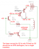
Hey Eric, you got me to thinking about the other transistors, PNP. Ignoring the resistor values, the below schematic should provide 12V to the motor?
**broken link removed**
Then all I have to do is add the diodes and the other three transistors for the other direction. Is it right to say that Q1 doesn't need a resistor on the base because it's actually on the emitter? Also it appears that the hFE of Q1 doesn't matter either as it will only make a very small change because we are dealing with small currents (20mA for Q1 C and E)?
Depending on the resistor on Q1 emitter it changes the mA of the Q2 base, how can we know the maximum mA that Q2 base can accept?
Last edited:
") . Yes I was planning on using a NPN darlington too because I couldn't find a regular transistor that could accept such low base current, I think I will look into Mosfets as you advise.
. Yes I was planning on using a NPN darlington too because I couldn't find a regular transistor that could accept such low base current, I think I will look into Mosfets as you advise.