Continue to Site

Welcome to our site!

Electro Tech is an online community (with over 170,000 members) who enjoy talking about and building electronic circuits, projects and gadgets. To participate you need to register. Registration is free. Click here to register now.

  • Welcome to our site! Electro Tech is an online community (with over 170,000 members) who enjoy talking about and building electronic circuits, projects and gadgets. To participate you need to register. Registration is free. Click here to register now.

How is this modulating?

Status
Not open for further replies.

throbscottle

Well-Known Member
I refer to this instructable:
https://www.instructables.com/id/Simple-surveillence-bug/
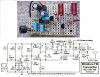
The author says it is an FM transmitter, but I'm rather curious to know how it is producing the modulation. I'm guessing the input voltage is causing the transistor's b-c junction to act like a varicap, but it would be nice to have a more informed opinion!

Thanks :)
 
That circuit is a variation of the common-base oscillator used for this type of "transmitter".

As for what makes it FM, I would instinctively agree with you that the audio voltage changes the base-collector capacitance and so changes the frequency.

A few years ago, someone here on ETO (from memory it was MrAl) opined that the change in collector current would effectively change the load resistance on the tuned circuit hence varying its resonant frequency.
I did start to make a tests jig to investigate this possibility, but real work got in the way and by the time I had sufficient playtime again, I had lost interest in the idea.

JimB
 
...the change in collector current would effectively change the load resistance on the tuned circuit hence varying its resonant frequency
I doubt that, the resosnant frequency is dependent only on L and C, any resistive loading should not be able to change it - it would only change Q of the LC tank.
 
I doubt that, the resosnant frequency is dependent only on L and C, any resistive loading should not be able to change it - it would only change Q of the LC tank.

Yes, conventional electrical wisdom does tell us that, however when the resistance becomes significant compared with the reactance, the resistance does have an effect.

Have a look here:
**broken link removed**
scroll down the page the section "Resonant Frequency using Impure Components" where he just presents us with an equation for resonance with a resistive term in it.

In my old college book, Electrical Technology by Edward Hughes (3rd edition, 1967), on page 313 he runs through a mathematical derivation of the equation

f = (1/(2 x Pi x L)) x sqrt(L/C - R^2)

which he finishes off by saying: "If R is very small compared with 2 Pi f L as in radio circuits.... f = 1/( 2 xPi x sqrt (LC)

JimB
(who really should learn LATEX notation one day).
 
That's an interesting viewpoint - change in collector current has effect of a change in resistance. Actually working out how much of an effect this would have on frequency is something I really haven't got the energy for...
 
Last edited:
I always saw it as a varicap be junction controlling the frequency, you only want a very small amount of mod to carrier, 80mc carrier with a 10kc mod is only around 0.01%, you could even 'pull' an xtal a certain amount.
 
Years ago I read that modulating the current creates phase modulation that the FM receiver interprets as FM. I don't have enough knowledge of RF to be sure this is true. Anyway, there is plenty of AM generated as well and if you change the components to resonate in the AM band, it works fine too.
JimB's eqs only seem to work if the R term is the resistance of the inductor rather than the parallel resistance at resonance. Expressing Fr as function of Q would make it easier to judge the amount of modulation that would occur.
Since Dr P beat me by a few seconds, I will add this here: if you use a 1N914 diode as a varicap the amount of modulation created is far less than that created by driving the base.
 
Last edited:
I have to agree, with am mod there is an fm component, the bandwidth of am if filters is designed with this in mind.
For broadcast receivers this might work at close range, for which the mentoned circuit is intended.
 
I have just been doing some digging, both in my junk pile and in past threads here on ETO.
I have found the tidied up version of the oscillator which I used as the basis of the discussions in this thread:
https://www.electro-tech-online.com...plifiers-and-oscillators.127836/#post-1063103

I connected up the oscillator and did a few basic tests to see that it still worked and then tried injecting an audio signal into the base to see what happened.
I got a reasonable FM signal, considering the basic nature of the circuit.

EinarA wrote:
Years ago I read that modulating the current creates phase modulation that the FM receiver interprets as FM. I don't have enough knowledge of RF to be sure this is true.
Quite right.
Frequency Modulation (FM) and Phase Modulation (PM) are more or less the same thing.
In days gone by, radios used for two way mobile communications, although identified as using FM, many were actually using PM.
If you are receiving an RF carrier modulated with a single audio sine wave, it is impossible to tell how the signal was generated, they are identical.

However, if we can vary the modulating frequency we find that for the PM signal, the deviation of the modulated carrier is proportional to the modulating frequency. If we double the modulating frequency we double the deviation.
Whereas for an FM signal, the deviation is constant as the modulating frequency is varied.
In both of these cases, this assumes that the amplitude of the modulating signal is constant.

I should also mention that for both FM and PM the deviation is proportional to the amplitude of the modulating frequency.

If the modulating signal is change in DC voltage, then for FM there will be a step change in carrier frequency, but for PM there will be a phase shift in the carrier, but no change in frequency.

EinarA also said:
I will add this here: if you use a 1N914 diode as a varicap the amount of modulation created is far less than that created by driving the base.
I don't think that the 1N914 makes a very good varicap diode, you may do better with a 1N4007.

Going back to to my statements in posts 2 and 4 of this thread about loading effects on the tuned circuit changing the frequency, I will make an effort in the next couple of days to try and run the loading experipment which I never got around to some time ago and I will report my results, good or bad.

JimB
 
The schematic is a nightmare (after all it is an Instructable) so I corrected it. Its emitter was shorted to its collector through C5. The value of the tuning capacitor C4 is much too high.
Millions of similar circuits are in Google but they all have a capacitor from the collector to the emitter to provide positive feedback.
 

Attachments

  • FM transmitter.png
    FM transmitter.png
    100.2 KB · Views: 401
The schematic is a nightmare (after all it is an Instructable)

You are right there AG!
The amount of rubbish that is propagated via Instructables is amazing.

JimB
 
The amount of rubbish that is propagated via Instructables is amazing.
Many Instructables are "designed" by kids who are only 10 years old and they know NOTHING about electronics.
 
I was aware that the receiver can't tell PM from FM. What I don't know is if any PM is occurring in the transmitter. I mentioned the diode as varicap because I think it will behave very similarly to the base-collector junction; i e not enough to explain the amount of modulation produced. I look forward to reading about your tests.
AG's attempt to correct the circuit has only made it worse. C5 was supplying the feedback needed for oscillation; it is also better to connect the antenna to the emitter. If this is supposed to operate in the FM band, then 5 to 10 pF is appropriate for both C4 and C5. A 47 to 100 pF cap across the emitter resistor is also recommended. ( Looking in a book, I see that this emitter cap should be less than the gain of the transistor times the feedback cap. Since people are trying to build this circuit with only general purpose transistors, it should only be 2 or 3 (or less ) times the collector-emitter cap.) The cap on the base is also too large by factor of 5 to 10. With no preemphasis this will only be good for muddy voice transmission.
 
Last edited:
AG's attempt to correct the circuit has only made it worse. C5 was supplying the feedback needed for oscillation
100pF is much too high for the positive feedback capacitor at 100MHz.

it is also better to connect the antenna to the emitter.
The signal level at the emitter is low but its impedance is low enough for a long antenna. The signal level at the collector is high but a long antenna loads down the circuit to stop oscillation. Also with the antenna at the collector then if anything moves towards or away from it then the frequency changes.

If this is supposed to operate in the FM band, then 5 to 10 pF is appropriate for both C4 and C5. A 47 to 100 pF cap across the emitter resistor is also recommended. The cap on the base is also too large by factor of 5 to 10. With no preemphasis this will only be good for muddy voice transmission.
I agree except my similar FM transmitter does not have a cap across the emitter resistor.
 
100 pF is far too large, but will still work; the circuit shown on the right has no feedback so will not oscillate. All theoretical discussions of this circuit include a cap to ground at the emitter. It seems to work just the same without it though. I think we agree on all the main points. It does seem that it is much harder to find a good version of this circuit than a bad one. ( This seems to be the case with almost all hobby circuits: the garbage far out numbers the quality.)
 
My FM transmitter has a tuned RF amplifier, a low dropout voltage regulator and pre-emphasis for excellent sound. Its range is across the street to a cheap radio or 2km across a wide river valley to my car radio and home stereo tuner.
 

Attachments

  • FM tx mod4 pic and schematic.jpg
    FM tx mod4 pic and schematic.jpg
    196 KB · Views: 363
I hope you didn't think I was implying your designs are in the junk pile. I use a similar circuit to rebroadcast audio around the house and yard, so no RF amp stage or antenna. I like to make Q1 a PNP so I can drive Q2 directly; saves Rs and Cs. I use an RF transistor (2N918 etc) for the oscillator.
 
However, if we can vary the modulating frequency we find that for the PM signal, the deviation of the modulated carrier is proportional to the modulating frequency. If we double the modulating frequency we double the deviation.
Whereas for an FM signal, the deviation is constant as the modulating frequency is varied.
In both of these cases, this assumes that the amplitude of the modulating signal is constant.

I don't get this (I don't know much about FM so forgive me). The case for PM sounds like what I would think FM should do, and the case for FM sounds like the change in frequency wouldn't be heard at the receiver. Think I need a drawing to illustrate the difference (sorry)...
 
I'll let others discuss PM vs FM. I dug up two equations. For a parallel resonant circuit with resistance, Fr equals Fo times the sqrt( 1 - ( 1/4Q^2)). For a Q of 20 ( a pretty low value for an Osc ), resonance frequency is shifted by .03% ; not very much.
Another reference gives the oscillation frequency of a Colpitts Osc as: W^2= 1/LCt + H22b/H11b * 1/C1C2. H22b is the collector conductance and H11b is the resistance looking into the emitter. So freq will vary with transistor bias, but by how much I haven't figured out yet.
 
Status
Not open for further replies.

Latest threads

Back
Top