Both your circuits have the capacitor directly on the output, so the response depends upon whatever the amp's output impedance is. That's not a normal or proper way to connect the capacitor so there's no good reason to try to analyze those circuits.View attachment 90929
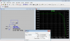
Can someone give me a hint about why the output voltage is less than the input in the right circuit? Where should I start to analyze it? The input is a sine wave with a magnitude of 1 volt and frequency 100Hz.
That's why my circuit has a resistor between the output and the capacitor (on second look I realize that R1 is not needed).
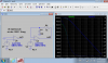
The feedback circuit is a simple LP filter that rolls off the AC feedback above its corner frequency (in this case the RC time-constant is 100F * 1kΩ = 100ks for a corner frequency of 1.59 microHz).
(I realize that 100F is not a practical capacitance but the simulator doesn't know that).
")
This means there is no significant AC feedback down to a below 1Hz , thus the output is the open loop AC response.
Last edited: