Continue to Site

Welcome to our site!

Electro Tech is an online community (with over 170,000 members) who enjoy talking about and building electronic circuits, projects and gadgets. To participate you need to register. Registration is free. Click here to register now.

  • Welcome to our site! Electro Tech is an online community (with over 170,000 members) who enjoy talking about and building electronic circuits, projects and gadgets. To participate you need to register. Registration is free. Click here to register now.

High power h-bridge

Status
Not open for further replies.

dreed75

New Member
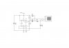
I need to make an H-Bridge that will be used basically as a heavy duty servo which is hooked to my microcontroller. It needs to be able to drive a motor that is about 20A @ 12V (wiper motor). I have searched for days on how to build one but I can't find one that is over 2A. I will probably have to make my own so I need some help.

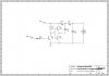
I found this page to be very helpful
**broken link removed**
but I can't find any PNP MOSFETS that are equal to a NPN MOSFET that I find.

Does anybody know of a PNP, NPN combo that will work for me?

Thanks
 
I searched for that chip on findchips.com but it wasn't found. Also on Yahoo, there was no matches.
 
The correct part number is IRF630N. Here's the link.

**broken link removed**

You should also consider a lower voltage (100V) but higher current rated device (23A), the IRF540N.

**broken link removed**

also

**broken link removed**

International Rectifier also has half-bridge MOSFET drivers to go with these devices.
 
Hbridge

i don't know if it will serve your purpose but you could check out the hbridge at the site Robot room, you'll get resources for other circuits as well
 
I guess for that high amperage you should use a relay based H-Bridge and have controll of it with ULN2003.
 
No, I would not use relays. I would do as suggested and use some very high current (read low RDSon) discrete mosfets. Building an h-bridge is very straightforward. I would pick the lowest voltage you are comfortable with and then find one with sufficient current handling.
 
"npn" and "pnp" is a term for bipolar. MOSFETs are called n-channel and p-channel, or PMOS/NMOS.

You would want to hook your two PWM channels to the n-channels pulling the outputs to ground. The p-channel is at 12V so the gate can't be switched directly, you will use a small MOSFET or npn to pull down the gate and a pullup pulls it back up.

PMOS is inherently lower gain and higher rds than NMOS. Not that you can't find PMOS with a lower rds than an NMOS, but in the end the biggest one PMOS you're going to find is worse than the NMOS, at least for a particular price. Go to https://www.digikey.com Seach for MOSFET, select p-channel, click "Apply Filters", then select the current you want AND, using the shift key, select every current higher than what you want.
 
You can also build a purely NMOS h-bridge. That reduces the number of different components and for equivalent RDSon values, N channel parts are lower cost and more readily available. All of mine are NMOS only. The trick is to use a small voltage doubler circuit to raise the gate voltage to 2Vcc so that the n-channel parts at the top of the bridge turn on. You have to be running high enough voltage so that the gate is 4 to 7 or more volts beyond the voltage at the drain node. For instance, with a 12V motor, you would generate 24V which is enough for the mosfets to work. You can use any of the ICL7660 doubler circuits. Alternatively, there are special parts such as the HIP4081 (i might be wrong about the part number) that is specifically designed to interface directly to an all n-channel h-bridge.
 
simple h-bridge solution

I have standardized on the IR331* for the high side of h-bridges. These parts have an adjustable current limit, up to 90 Amps. The current limit is set with a single resistor. The output current is proportional to the current limit voltage so the current can be measured with a simple ADC. They are on when the input is off so they can be driven with a small mosfet directly from a microprocessor. The current limit makes the whole h-bridge very robust. I have used it with wiper motors and larger motors. By monitoring the bridge current I can operate motors until they stall, avoiding the need for limit switches and circuitry. The overcurrent response is fast.

These work well with motors but the overcurrent response is so fast that they won't drive headlights, which have over 10:1 in rush (2 60w bulbs have over 100A in rush cold).

If you want more info you can e-mail me at stephen@copper.net - I probably won't check this site very often. If you want a couple of surface mount IR 3312 (30A) or IR3310 (100A) I could sent them to you. This offer is only good for a few people.

- Stephenvb
 
YAll of mine are NMOS only. The trick is to use a small voltage doubler circuit to raise the gate voltage to 2Vcc so that the n-channel parts at the top of the bridge turn on. You have to be running high enough voltage so that the gate is 4 to 7 or more volts beyond the voltage at the drain node. For instance, with a 12V motor, you would generate 24V which is enough for the mosfets to work. You can use any of the ICL7660 doubler circuits. Alternatively, there are special parts such as the HIP4081 (i might be wrong about the part number) that is specifically designed to interface directly to an all n-channel h-bridge.

Not to hijack but -- thanks for posting this. The lightbulb just went on for me on this topic. :D
 
h-bridge

Yes, you can make a vltage doubler and use all n-mos. I use the IR331* and suggest it because you don't need a voltage doubler and because it provides short circuit protection. At such high currents shoot-through, a wiring error or a short destroys the mosfets, connectors and circuit boards. In an h-bridge high side protection also protects the low side mosfets. I make mistakes and I have had wires come loose and motors fail so this is important to me. If you never have these things happen it would be of no use at all.
 
Use IRF 840 and IRF 9520 combo for Hbridge motor drive...
They are working great for me....
Stay away from Relays young man!!!!:D
 
Here is all you need two of them make a full H-bridge **broken link removed**
 
There is one point that needs to be brought out here ...
The mosfet gates are essentially capacitors ..... activated by a charging and discharging current.
If your control signal switching frequencies are too great, the mosfet might be operating at a point on the performance curve where it could overheat or be otherwise damaged. Also, check the charts given in the data sheet for the specific part that you are using.
There were one or two informative articles regarding this subject in Circuit Cellar Magazine, earlier this year .... maybe Dec. 08, Jan. 09.
 
Yes you are right.Even I have heard sound form MOSFETS while giving PWM to it.But if you consider the general use than there is nothing like that.IRF 840 and IRF 9520 works till 20 kHz.And I think that is too higher.So you can use them with proper isolation like optoisolater,transistor etc.

Another problem while dealing with MOSFETS is Floating.That is when you dont give any signal and supply is connected with D and S than sometimes they get heated and excess of heat burns them out.we need some extra protection circuit for that.
 
For setups like this i used simple transistor voltagedoublers
(when i had MCU to provide a clockpulse)
If i cant spare the MCU pin i use the same idea but with 555 as pulse generator .
(i attached both setups)
About your mosfets ,i would use all n-mosfets (and forget about irf540) .
Nowadays you have much better mosfets then irf540 .
I would look at something like irf1407 or something with simular or even lower RDSon .
Just have a look at the IRF website and look for mosfets for synchronous rectification .
This will save you a lot of heat in the mosfets and reduce the amount of heatsinks .
About your gatedriver ,you can either use a gatedriver ic like the ir21xx and keep the bootstrap capacitor charged with a chargepump .
(IRF has application notes on this topic)
https://www.electro-tech-online.com/custompdfs/2009/06/an-978.pdf
Or just build it discrete with a few transistors for levelshifting and gatedriving .
Both methods would do the job reliable and simple.
Good luck .
 

Attachments

  • doubler555.jpg
    doubler555.jpg
    29.4 KB · Views: 1,158
  • voltage doubler.jpg
    voltage doubler.jpg
    51.9 KB · Views: 1,933
Hi,

I posted this on a different thread but in case you didn't see it perhaps it will be useful.

I found this chip (VNH2SP30) used by robot hobbyists. It's an H-bridge originally used in cars to driver power windows and the like. It's rated at 30A burst and about 14A continuous with no heat sink. Pololu sells carrier boards if you don't want to do surface mount. I bought some from Digikey for about $15 (CAD).

Pololu - VNH2SP30 Motor Driver Carrier MD01B

Dr Iguana
 
Status
Not open for further replies.

Latest threads

New Articles From Microcontroller Tips

Back
Top