Continue to Site

Welcome to our site!

Electro Tech is an online community (with over 170,000 members) who enjoy talking about and building electronic circuits, projects and gadgets. To participate you need to register. Registration is free. Click here to register now.

  • Welcome to our site! Electro Tech is an online community (with over 170,000 members) who enjoy talking about and building electronic circuits, projects and gadgets. To participate you need to register. Registration is free. Click here to register now.

Help with dynamic test load

Status
Not open for further replies.
Oh, well that's a problem then. Funny, the first version of this actually used a precision 2.5v reference with the pots for the reference signal.
Since the supply is 12v on the money and wouldn't have any headroom for a 12v reg, could I use a 9v battery or 7809 to power the opamp and provide reference voltage to the pots? The only problem I can see with a battery is if I go back to a big power module, they need a good bit of drive current. More than a 9v could supply for too long.
Everything runs to the star ground except the fan and the power led. The 510ohm resistor literally ties directly to star gnd and pin3.
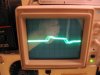
The only problem I can see with the 12V switcher is that it makes it difficult to view the transient response test. A little switching noise in your load should not be a problem. If you want to clean it up with a 2.5V reference, I can post a schematic if you don't have one.
Regarding the 9V battery, the voltage may be a little low for the gate drive of the MOSFET circuit at max current. As far as the battery lifetime with the power module is concerned, the op amp short circuit current is 40mA, and can only supply about 10mA reliably. I'm not sure that is enough if the load is hundreds of amps.
 
Ok, linear wall wart it is followed by regulation.

When I get another triple darlington module (only about $20 surplus) for the largest of the three units I'm building, I'll put the common collector stage back in to get the needed current. I'll report back tonight. Thanks!
 
i'm a little late to the party, but do you have a list of specifications that this load generator needs to meet? are there any load slew rate requirements?

Also, I would suggest - unless the testing requires longer on-times - to cap the duty cycle at 10%. There's still a lot of power to dissipate, but low duty cycles should help to keep that to a minimum. The period will have to be determined by the specs of the supply - expected settling time, etc.
 
Hi OutToLunch,
I'm actually building three different sizes of these. One to about 500W, one to about 1.8kW, and the third Probably to 5kW. The reason for three is location and portability. These will be used on existing supplies to periodically check general health.

Duty cycle will mostly be short, say 15mins, but could be all day if we're torture testing. The units (except for the largest) are surprisingly compact already.
 
Ok, did a lot to this last night and today. Built a new psu with good regulation and better isolation from the cooling fan. Fixed reference voltage section, and replaced the 100k pot with a 1meg.
The first pic is 6Hz across the sense resistor without compensation.
The second is with .03uF compensation.
Seems like that value is a good compromise, but how far should I go with capacitance here? I found that with enough, it did exactly what a large value should do- squash and flatten the square wave.
 

Attachments

  • eLoad no Comp.jpg
    eLoad no Comp.jpg
    200.8 KB · Views: 154
  • eLoad .jpg
    eLoad .jpg
    192.8 KB · Views: 150
Actually, it appears to be fine without compensation. I think the droop is due to either the input coupling capacitance, or having your scope AC-coupled.
If you want to leave in the compensation, It won't hurt anything unless you decide to make the current controlled by an external pulsed voltage source.
 
Well thats encouraging. I did have the scope on ac coupling. Should I try viewing it on dc?
I can't load it up to where the other designs have failed until I get parts, but I'll report back when I do. Thanks!
 
Well thats encouraging. I did have the scope on ac coupling. Should I try viewing it on dc?
The problem with DC is you will probably have a small pulse waveform with a large DC offset, making the response hard to see. Try raising the frequency of your test oscillator by a factor of 10 or more, and keep the scope on AC.
I can't load it up to where the other designs have failed until I get parts, but I'll report back when I do. Thanks!
Yeah, I'm still worrying about why it died. The frequency stability will change as you add more MOSFETs, if that's what you are planning.
 
Ok, I'll try raising the frequency.
I've ordered a few of the large power modules for the units because I got them for less than a couple tubes of the mosfets and I don't have to worry about matching. Probably just need to add a big emitter resistor when I parallel a couple of them in the largest unit.
Now that I have a clean supply and better stability at low power (which I didn't have before) I'll be interested to see what it does as well. All three designs failed when I put an old 24v 750W switcher on them. It was ok until I hit an imaginary line and it became unstable VERY fast.
 
Raising the frequency will likely cause more heat dissipation in the pass element due to increased switching losses. I would recommend reducing the duty cycle to no more than 10%. You had mentioned your duty cycle is 15mins - i mean the duty cycle of the individual load pulses. For example - if the loading period is 1msec, the time that the load should be applied would be 100usec. You can obviously increase the period but keep the duty cycle low to reduce power loss across the pass device. This should still allow you to see how the power supply responds to the load.
 
Raising the frequency will likely cause more heat dissipation in the pass element due to increased switching losses. I would recommend reducing the duty cycle to no more than 10%. You had mentioned your duty cycle is 15mins - i mean the duty cycle of the individual load pulses. For example - if the loading period is 1msec, the time that the load should be applied would be 100usec. You can obviously increase the period but keep the duty cycle low to reduce power loss across the pass device. This should still allow you to see how the power supply responds to the load.
The frequency we were talking about is that of the small superimposed AC test signal which I recommended for looking for possible oscillatory tendencies.
I think he is determined to test his supply under a DC (not pulsed) load.
 
then it certainly would not be a dynamic load as alluded to from the title of the thread - or at least my interpretation of a dynamic load. perhaps adjustable load is better.
 
Dynamic Load, Electronic Load, eLoad, Electronic Rheostat. These terms seem to be interchangeable between manufacturers and EE journals.
 
Ok, got a few power modules in and hooked one up. Tested at 10v 30A and it seemed to be ok.
Two strange things though, there is now an "envelope" of noise about 4ms wide every 4ms or so. It's only about 10mV, but that's new. The other thing is tracking is very slow. When the adjustment from no load to max of the range is made, it takes a good 2 secs for it to follow. Same happens from max to min. Gate voltage just gradually decreases.
Do you still have the test oscillator connected? The big input coupling cap will cause the slow response, and the oscillator may be causing the noise.
Did you check the response to the test oscillator after you put in the power module?
 
Last edited:
Doh! That certainly would explain the slow response. It was connected but not powered up.
Here's another square wave shot with the power module in. I've got one more vertical range left on 1X if you need more detail.
 

Attachments

  • With Powerex.jpg
    With Powerex.jpg
    208.4 KB · Views: 149
Doh! That certainly would explain the slow response. It was connected but not powered up.
Here's another square wave shot with the power module in. I've got one more vertical range left on 1X if you need more detail.
That looks really good. I hope you mysterious problem is gone.:)
I don't see the noise bursts on this scope photo. What point were you monitoring?
 
Last edited:
Excellent. Yeah the noise bursts are really low level. They can be seen moving through the waveform but doesn't show in the fuzzy pics. It appears to be related to wiring around the power module as it changes a bit when the long runs are moved around. I'm wondering if it's from the raw 12v ac that runs from the back to front panel power switch. It runs pretty close to the module and sense resistors.
I'll go ahead and load it to about 750W tonight and report back. Thanks!
The noise probably is crosstalk, as you surmised. Could the bursts be 8.33ms apart? That would be coming from something that is powered by the mains.
 
Ok, well nothing blew up this time. I maxed out the circuit with a .1ohm sense resistor at 26.0 amps with the 24v industrial switcher. What's odd is there was a waveform with the switcher across the sense resistor. Still trying to get a good pic of it as it's pretty faint. It's a sine wave, but the troughs are all the same while the crest of every other wave is about 10mV higher. The peaks are also a little fuzzy. Could this just be the nature of the switcher? It's probably designed to drive electromechanical stuff that may not care about a little ripple if that's what it is.
 
Status
Not open for further replies.

Latest threads

Back
Top