jmarmontgomery
New Member
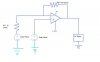
Here is the the Solar Traccer Design That I Am Using...However, I Got it hooked Up to the breadboard and it is not working...I Believe I Have It Hooked Up Correctly, but Id Rather get my Design Reviewed first, then check to see if I have solid connections on my breadboard.
I am using the ever so common:
OP AMP 741
400 mA/0.5 V Solar Panel
10 Ω Resistor as R1
10M Ω Resistor as R2
3.0 V Power Source-------> (In The Diagram, I have it listed as 1.5V)
a Small DC Motor..
FIrst things first, I know the motor works, I connected it to my 3.0v Power Supply (a Battery Pack wired in Series)...Solar Panels Works....So now, I Need everyone's Help to verify that my diagram is correct.
PLEASE PAY SPECIAL ATTENTION To the Polarity of the Power Supply in Regards to the OP AMP...
<a href="http://smg.photobucket.com/albums/v350/gdupgodfather/?action=view¤t=CircuitDiagram.jpg" target="_blank"><img src="http://img.photobucket.com/albums/v350/gdupgodfather/CircuitDiagram.jpg" border="0" alt="Photobucket"></a>