Clarkdale44
Member
Hello
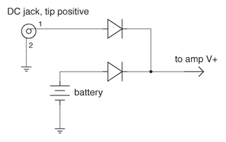
I have a device which needs to stay on, when the mains power fails, it takes about a second before the battery kicks in, this makes the device reboot and it takes a while to get everything back together. So i wanna add a capacitor in parallel to the device, so that it could power the device for just 1 second until the battery takes on. I just want to know how to calculate its capacitance.
My device is rated at 1 amps, takes 9 volts input.
Regards!
")