Ctrl_Alt_Del
New Member
on this page :
https://members.tripod.com/~wvsp/light1.html
i dont understand how to make the transformer.. :roll:
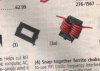
what is Radio Shack "Noise Eliminator Kit" ?
and how to begin winding, wire, etc.. :?
can anyone explain me with picture please..? :lol:
https://members.tripod.com/~wvsp/light1.html
i dont understand how to make the transformer.. :roll:
what is Radio Shack "Noise Eliminator Kit" ?
and how to begin winding, wire, etc.. :?
can anyone explain me with picture please..? :lol: