yngndrw
New Member
Hi,
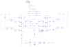
I am designing a H-Bridge to be used with a PIC for a stepper motor controller. Attached is the circuit which I've come up with.
There are some test things there, but generally the PIC will set the Direction, Brake and the variable voltage source. (Above the current sensor op-amp.) The MOSFETs will be IRF540N and IRF9540N.
I am aiming for a switching frequency of around 20KHz, above the threshold for human hearing. However due to the design it will run at it's own speed. I tried to limit the frequency using the 10K resistor and 5nF capacitor next to the op-amp.
The reason for this hardware PWM solution is so that the PIC program can be much simpler. It means that the user can set the current limit through a potentiometer and no ADC use is required. It just needs a dual DAC. (One for each coil.)
I don't have the components to test this at hand so I thought that I'd ask for advice on here. Some of the component values (MOSFETs) are wrong because the program I used doesn't have IRF540N / IRF9540N.
I also intend on building the H-Bridge on a PCB without the current limter so that I can use it for other projects. I will use TTL buffers so that it can accept 5V and 3.3V signals.
Note: The resistor and inductor in the middle are to model my stepper motor coil.
My main questions are:
1) Are there any general problems with this design ?
2) Will there be any issues with this, seems as it doesn't have a "fixed" PWM frequency ?
3) Any suggestions ?
Thanks for your time,
-Andrew.
Attachments
Last edited:
