Continue to Site

Welcome to our site!

Electro Tech is an online community (with over 170,000 members) who enjoy talking about and building electronic circuits, projects and gadgets. To participate you need to register. Registration is free. Click here to register now.

  • Welcome to our site! Electro Tech is an online community (with over 170,000 members) who enjoy talking about and building electronic circuits, projects and gadgets. To participate you need to register. Registration is free. Click here to register now.

Electronic motors

Status
Not open for further replies.

2PAC Mafia

Member
Hello,

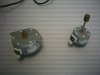
I would like to know the function of the pins (I/O) we can find on this kind of motors. On the picture there are 2 Minebea electronic motors I have, I think from a damaged videocassette, on these ones there is an small PCB with a small connector of 6 pin.

I would like to play a little bit with them and then understand the function of each pin but I don´t know what kind of inputs I should apply on them to make them run...

Thanks.
 

Attachments

  • phto0036.jpg
    phto0036.jpg
    311.7 KB · Views: 1,136
From the look of them (particularly the left hand one), I would suspect they are stepper motors.

Try rotating them gently by hand, do you feel a large number of small 'steps' as you rotate it? (probaly 200 or so for a full rotation).

If they are steppers, you have to provide stepping signals for them, there are loads of stepper tutorials on the net - try google.
 
Hello Nigel,

yes, I turned them and I felt those steps you mean. OK, then I´ll look for step motors if I find something useful at google.

Thanks.
 
MINI STEPPER MOTOR: NMB Brand, model # PM35S - 048. 24V DC Operation, 50ohm coil resistance, 6 wire. 7.5degree step angle.
Measures 42mm long, 32mm wide & 15.5mm high:
**broken link removed**

NMB has a website as well , that should be worth exploring.
 
You will need a certain binary sequence to run steppers, and possibally a transistor driver array.

Most steppers have a standard code, however, companies like to be different.

to test the sequence, simply put each lead of the stepper as a input to the base of a transistor (a general one will work), and put a LED in relation to the collector so it turns on when pulsed, and the emmiter to ground using a 10 ohm resistor. Each lead will have it own transistor in sequence from pin one to the last. Spinning the shaft will repeat the sequence over and over. One of the pins is power.

Luckily those steppers are 4 bit binary driven.
 
Do a search on Google, there are ways of checking the resistance/continuity of the wires to determine the proper stepping sequence.
 
Status
Not open for further replies.

Latest threads

New Articles From Microcontroller Tips

Back
Top