:?:
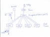
I built a 8 shaft monitor (missing pulse detector)
4 dual timers, 1 - 8 input Nand gate,
& a 555 timer that operates relay.
When all is running 8 diods are lit up.
If one of the 8 shafts slow down & stop, the one diods flickers
& go out, then the 555 timer opens up the relay
then every thing including the monitor goes dead.
What I would like is some kind of latch??
to tell me which shaft was the problem?
Ben
 Sorry I don't know how to send a schematic. Ben