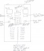
Hey all! I'm looking to build an electronic dart score board. Something that does the same function as the dart master III. **broken link removed**
They are like 300 bucks, but we want it to look a little different, but provide the same function. I'm very good with my soldering iron, as well as the fabrication. But I have no idea with the actuall programing and circuit design. I have down some flash programing on my xbox's and worked with an eprom programmer back in my cisco upgrade days.
So far I have the aluminum to design my housing, and installing the lcd panels and switches are pretty straight forward. But I have two questions,
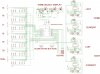
1. Can I make the circuit and controller for less then the cost of $300?
2. Is there anyone who can help with the programming.
I need the controller to be able to play cricket, 301, 401, and 501. I know the easy way is to just buy the dart master, but we want it layed out slighty different, and bigger led screens, as well as different color leds. Plus I like the challenge.
They are like 300 bucks, but we want it to look a little different, but provide the same function. I'm very good with my soldering iron, as well as the fabrication. But I have no idea with the actuall programing and circuit design. I have down some flash programing on my xbox's and worked with an eprom programmer back in my cisco upgrade days.
So far I have the aluminum to design my housing, and installing the lcd panels and switches are pretty straight forward. But I have two questions,
1. Can I make the circuit and controller for less then the cost of $300?
2. Is there anyone who can help with the programming.
I need the controller to be able to play cricket, 301, 401, and 501. I know the easy way is to just buy the dart master, but we want it layed out slighty different, and bigger led screens, as well as different color leds. Plus I like the challenge.