Continue to Site

Welcome to our site!

Electro Tech is an online community (with over 170,000 members) who enjoy talking about and building electronic circuits, projects and gadgets. To participate you need to register. Registration is free. Click here to register now.

  • Welcome to our site! Electro Tech is an online community (with over 170,000 members) who enjoy talking about and building electronic circuits, projects and gadgets. To participate you need to register. Registration is free. Click here to register now.

DPDT Problem

Status
Not open for further replies.

adamcruzster

New Member
Hey guys,

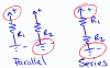
My name is Adam and I'm new to electronics. I have been asked to use a two 12V incandescent lamps in series (or parallel) with a 12V DC power source using a DPDT switch. The series/parallel connections must be controlled from the position of the switch. One position must bring circuit to series, and the other position of the switch should make it parallel. After trying to wrap my mind around this, as well as several hours spent in Multisim today -- this one is beyond me. Any help would be greatly appreciated guys.
 
Last edited:
Hi Adam,

You don't need to use Multisim for this problem; a simple pen and paper will be more than sufficient.

Have a look at the attached drawing; you'll see there's a series connection of two resistors, and also a parallel connection of the same two resistors. Note in both configurations one of the terminals of R1 remains attached to the positive supply, while one of the terminals of R2 is always attached to the negative supply... so your DPDT switch could just be used to change the connections of the remaining terminals of the resistors (or light bulbs).

Good luck!
 

Attachments

  • series parallel.png
    series parallel.png
    8.2 KB · Views: 345
if you look at circuit posted by dougy83, and consider using SPDT to switch one of the resistors, you should easily see how to to that part. for complete solution, you ue the other half of the switch (second SPDT)
 
I've considered and reread what both of you have posted, and I'm just not understanding. Here is what they are asking me for exactly

"Draw (or MultiSim) a schematic diagram showing how to use a DPDT switch to connect two 12V incandescent lamps either in series or parallel with a 12V DC power supply. The series or parallel connections must be controlled by the position of the switch. For one position, the 12V lamps must be in series with the DC power supply. In this position, the lamps will be dim because each bulb will receive only 6V. In the other position, the the lamps must be parallel with DC power supply. In this position the lamps will be much brighter because you will get 12V across each bulb."

I looked at the what dougy83 wrote out (thanks btw, dougy!) and I am really just not seeing it. Even tried to put this together and a breadboard and had no such luck. Any help would be greatly appreciated guys, thanks!
 
Is this what you are looking for?

switch.png

Sorry for the sloppy schematic. I couldn't find the specific symbol I wanted. The switch terminals are the green circles. The redish line represents which terminals are connected in each position. When the contact is up, the resistors are in series. When down, they are in parallel to the 12V source and ground.

I think the lesson here to learn is that when wiring a DPDT switch, always think of crossing.

John
 
Last edited:
there are several solutions, here is example of some of them and how i got to them
 

Attachments

  • ser-par.png
    ser-par.png
    9.5 KB · Views: 338
there are several solutions, here is example of some of them and how i got to them

Thank you everyone so much. I'm starting to think maybe this is not the field for me. You have all been very helpful and quite honestly I'm STILL not getting it :confused:. I do understand Panic Modes, just not used to this type of schematic. I understand the flow in respect to ground, however, the way I am supposed to draw it out is different.
 
@panicmode - nice job

@adam
Follow the current. Start at VCC and try to find ground through R1. Then start at Vcc and try to find ground via R2.

If you have two paths through R1 and R2 to ground , then R1 and R2 and in parallel.

Flip the switch. Now do the maze puzzle starting at Vcc (in) and try to find out (gnd) while passing through R1 and R2.

getting there is a little harder, but starting with R1 and R2 connected together at one spot makes some sense.

Th n-way switch problem is difficult too if you haven't seen it. You can have n switches and any one of them can change the state of the lamp. The 3-way switch arrangement is used for stairs. The concept is extensible to n-way.
 
@adam,

i'm sorry that you still have trouble with it. it is really not that complicated, just draw out EVERY step of what you know and what you need.
here is a bit longer version, i hope it helps. the key point is how SPDT switch works. there are three terminals:
C - common
NO - normally open
NC - normally closed

either NO or NC are connected to C (except during transition while moving switch).

DPDT is the same, it is just pair of SPDT ganged together.
 

Attachments

  • par_ser_2.png
    par_ser_2.png
    31 KB · Views: 298
Thank you so much guys. After hours of tedious staring, I understand. I want to thank you guys for the help and I'll be sure to come back should I run in to another problem I just can't crack
 
And sure enough... I've been hit again with a switch problem..

I have to show how two SPDT switches can be wired basically to turn on and off a light from two different locations with a 12V source. Any guidance would be greatly appreciated. I literally just drew out about 20 schematics and I'm trying to prevent the frustration I had with the DPDT question. Any help would be great!
 
Your post must still be in moderation, but I got the email version.

I probably tackled the 3-way switch problem back in grade school sometime. Way before the Internet. It's still tough to understand the terminology used for electrical such as 3-Way switch for SPDT and 4-Way switch for DPDT.

Warning! When you switch fields, don't assume anything. Power cords are colored Black, white and Green. Which one is hot? It's customary to use red for + and - for black for electronics, but don't apply this convention to thermocouples. Red is always negative. Just a warning.
 
i'd say don't add too much information, it will just confuse him.
he is not working with thermocouples or AC.
 
This is the classic landing light switch problem where a light can be switched from either the upstair landing or at the bottom of the stairs. Practically every two storey house has one wired.
The source voltage is irrelevant of solving the problem but has been used by your tutor for safety reasons should you have to build it to prove it works.

Tip. Which part of a SPDT switch is common and never switched out of circuit?

If I post the simple solution, you will not have learned anything.
 
Status
Not open for further replies.

New Articles From Microcontroller Tips

Back
Top