Continue to Site

Welcome to our site!

Electro Tech is an online community (with over 170,000 members) who enjoy talking about and building electronic circuits, projects and gadgets. To participate you need to register. Registration is free. Click here to register now.

  • Welcome to our site! Electro Tech is an online community (with over 170,000 members) who enjoy talking about and building electronic circuits, projects and gadgets. To participate you need to register. Registration is free. Click here to register now.

Diode ID help

iceotty

New Member
Hi all,
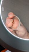
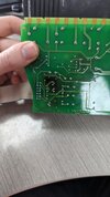
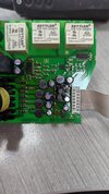
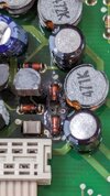
Don't know if this is even possible but would anyone be able to get a rough ID on this diode? I don't have a schematic for the circuit board and there aren't any part numbers on it. One of the (not blown) diodes next to it has "something" V 5 on it, if that helps at all. They may have been part of a rectifier circuit but I'm not 100% on that.

Thanks for any help
 

Attachments

  • vibro diode.jpg
    vibro diode.jpg
    1.3 MB · Views: 76
Surface mount components are rarely identifiable, you need to consult the service manual (which is unlikely to be available) to identify it.

Posting details of exactly what the device is, GOOD pictures of the PCB, and what's happened to it may allow members to make suggestions. Is the diode short circuit?.

From that picture, all you can say is it's a surface mount diode - there's no indication as to what type of diode it might be.
Okay, I figured they wouldn't be identifiable but it was worth a shot. The diodes don't have an obvious fault, testing them they work as they should, but the board around them has blackened as if they've had a short and burned something out. I've attached photos of both sides of the board, and the diodes before I removed them.
The device is a Bruel & Kjaer Vibrocontrol 920, I opened it up because it was having a fault with the power - it kept rebooting itself, which makes me think they're part of the ac-dc rectifier.
 

Attachments

  • PXL_20240102_103438737.jpg
    PXL_20240102_103438737.jpg
    1.8 MB · Views: 71
  • PXL_20240102_103500510.jpg
    PXL_20240102_103500510.jpg
    2.3 MB · Views: 82
  • PXL_20231229_113621408.jpg
    PXL_20231229_113621408.jpg
    1.2 MB · Views: 75
Okay, I figured they wouldn't be identifiable but it was worth a shot. The diodes don't have an obvious fault, testing them they work as they should, but the board around them has blackened as if they've had a short and burned something out. I've attached photos of both sides of the board, and the diodes before I removed them.
The device is a Bruel & Kjaer Vibrocontrol 920, I opened it up because it was having a fault with the power - it kept rebooting itself, which makes me think they're part of the ac-dc rectifier.
If the diodes check OK, then they are OK - if they had gone short, they would still be short.

It's more likely something else has caused them to overheat, and the prime suspects in switch-mode PSU's are electrolytic capacitors going high ESR. If you have an ESR meter, then check the electrolytics round that area (in circuit, while powered down) - if you don't have an ESR meter, and the PSU still runs, then check for ripple on the electrolytics with a scope (if you have a scope). Sometimes, if you're lucky, there are obvious visual signs of distress on the capacitors, such as doming or leaking, but sometimes they are still visually perfect.
My multimeter does have a capacitor test function (I presume this is an ESR). Checking the capacitors was a good shout - a few of them do seem to have gone open circuit, and a couple of others are reading double the capacitance that they're marked up as. Checking them all visually they look fine as you said. I'll try replacing the ones that seem faulty.
There's some transistors in that area too, are they likely to have been damaged? I'm not so sure how to test those.

Thanks for your help!
 
My multimeter does have a capacitor test function (I presume this is an ESR).

No, it's not an ESR meter, which is a specific type of test which is a very important piece of equipment these days for doing electronic repairs - probably the most important for repairs.

Checking the capacitors was a good shout - a few of them do seem to have gone open circuit, and a couple of others are reading double the capacitance that they're marked up as. Checking them all visually they look fine as you said. I'll try replacing the ones that seem faulty.
There's some transistors in that area too, are they likely to have been damaged? I'm not so sure how to test those.

Thanks for your help!

With a crude capacitance range on a multimeter, you need to take them out to test them, and they 'may' read OK even if faulty - as ESR isn't the same as capacitance. You 'could' be lucky, but having tested tens of thousands of electrolytics the vast majority of faulty ones fail ESR testing, while the capacitance value is still within specification.

If they are reading double in-circuit, that's because there are two capacitors in parallel - both of which are passing the capacitance test.

But if you find some which read very low when removed, they are likely to be faulty.

I'd change any low reading electrolytics you find first, then see what happens.
 
No, it's not an ESR meter, which is a specific type of test which is a very important piece of equipment these days for doing electronic repairs - probably the most important for repairs.


With a crude capacitance range on a multimeter, you need to take them out to test them, and they 'may' read OK even if faulty - as ESR isn't the same as capacitance. You 'could' be lucky, but having tested tens of thousands of electrolytics the vast majority of faulty ones fail ESR testing, while the capacitance value is still within specification.

If they are reading double in-circuit, that's because there are two capacitors in parallel - both of which are passing the capacitance test.

But if you find some which read very low when removed, they are likely to be faulty.

I'd change any low reading electrolytics you find first, then see what happens.
Okay, I'll order an ESR meter and in the meanwhile I'll replace the caps that are clearly faulty. Thanks again! I'll post an update if/when I get it working
 
Something like this, which are widely available, will give fairly accurate readings if you only need it for occasional use.
Yes, it's a good cheap solution, and has LOAD'S more uses as well - plus they are great fun to build if you buy them as a kit.

ESR wise, you probably need to remove the capacitor from the board though.

I've built about four of various types of these now, and they are incredibly useful - for example stick a transistor in it, and it tells you if it's NPN/PNP, and which wires are C, B and E. They are also great from telling what values modern 1% resistors are, as the colour codes are very poor.

When I was working as a service engineer I used a Peak Atlas ESR meter https://www.peakelec.co.uk/acatalog/esr70-capacitor-esr-meter.html and those are really nice - but I do very few repairs now.
That Peak ESR70 is the one I was looking at getting! I don't do a ton of electronics repair but I'd like to, and the price is less than the cost of a new controller anyway
 
That Peak ESR70 is the one I was looking at getting! I don't do a ton of electronics repair but I'd like to, and the price is less than the cost of a new controller anyway
I see that one is now the 'Gold' version - I think mine is the older 'Plus' version?.

Interestingly, they are designed (and perhaps built?) 20-25 miles from me, on the same industrial estate as a friend of mine - who in fact they give samples to, to test for them (he repairs TV's and electronics - and now sub-contracts for us at work).
 

Latest threads

New Articles From Microcontroller Tips

Back
Top