Electro Tech is an online community (with over 170,000 members) who enjoy talking about and building electronic circuits, projects and gadgets. To participate you need to register. Registration is free. Click here to register now.
Welcome to our site! Electro Tech is an online community (with over 170,000 members) who enjoy talking about and building electronic circuits, projects and gadgets. To participate you need to register. Registration is free. Click here to register now.
No need to reset the 4017. For every 10 pulses its reseting. If you want to reset to 9 pulses, simply you must reset the 9 th output in the 4017.Its easier if you take a decade counter for this like 4026.Specially designed for segments. Only needs the correct 1 second pulse.
No need to reset the 4017. For every 10 pulses its reseting. If you want to reset to 9 pulses, simply you must reset the 9 th output in the 4017.Its easier if you take a decade counter for this like 4026.Specially designed for segments. Only needs the correct 1 second pulse.
I have a general question to ask. One second accurate pulse is a problem for many people, even for PIC’s. Can’t they build a crystal for 1Hz.or a small IC or a package which gives accurate 1 second. In analogues all the time we use pulse generators to get a pulse adding some more extra parts to the circuit. Why is this?? Any comments from you experts….
This is how the display counts to and is set to zero at 60.
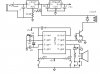
The 1 second pulse from (diagram 2) is connected to the input pin 1 of IC11. This IC counts from 1-0 and displays the seconds units via the LED display. When the count reaches 0 on the 10th pulse the IC resets and outputs a pulse to IC9 input pin 1. This advances the seconds tens display by 1. Every 10 seconds IC9 is stepped by 1 until the count reaches 60 seconds or 6 pulses to IC9. IC9 & 11 are reset by IC2d and IC12a. This reset also steps the Minute Units by 1 via the Set Secs switch not operated, IC7a and IC7b to IC8 input pin1.
You can find a full description of the whole circuit and all the diagrams om this web site. **broken link removed**
Years ago, National Semiconductor made the MM5369 IC which operated from a 3V to 15V battery and a cheap crystal from a colour TV and it had a 1Hz output. They stopped making it when all the hobbiests bought one and Chinese clocks became very cheap.
Years ago, National Semiconductor made the MM5369 IC which operated from a 3V to 15V battery and a cheap crystal from a colour TV and it had a 1Hz output. They stopped making it when all the hobbiests bought one and Chinese clocks became very cheap.
I have a similar project using a Standard Electrical Time (SET) slave clock made in the USA. (My interest in these clocks developed when I read about the British Synchronome system and the Shortt astronomical clock.)
I considered running my master off a 32768hz watch crystal, but decided in favor of a 4 mhz time base. There are 86,400 seconds in a day so a 1 hz error in the watch crystal translates into a three second error daily.
My controller is based on a crystal controlled PIC microcontroller. Each instruction cycle takes 1 microsecond so I use a standard 60,000,000 instructions per minute for the base pulse. I modify the pulse count to achieve sync with WWV, our time standard. In my present controller a pulse count of 60,000,620 provides an error of within a second over the course of a week.
This first controller used a PIC 12F508. Two pins operate the STOP and ADVANCE switches. One pin sends a seconds pulse out to LED or a piezo speaker. One pin operates the TIP120 switching transistor that drives the clock. The final two pins drive the crystal.
Delay loops perform the timing and the MPLAB simulator allows precise testing of the loop periods. No interrupts are needed.
A new controller uses a 14 pin PIC. Because my slave clock requires 24 volts at 100ma I decided to use a wall transformer to drive the clock and controller. There is no battery backup. So an LED is programmed to light if we've suffered a power failure.
Two additional switches allow the clock to advance or retard its seconds pulses against the WWV standard. This allows feeding the WWV and clock pulses into a scope to precisely sync the two.
Its been an interesting project. I've been impressed with the consistency of a regular microprocessor crystal at room temperature. In my first controller I unsuccessfully tried to vary the crystal frequency by using a variable capacitor in the crystal line. I've since decided that changing the delay period in software is a better approach.
Hi bobledoux
Your clock and setup sounds interesting.
My clock was based around a BT clock electronic 1a. These exchange master clocks replaced the old pendulem driven clock 36 but had an LCD display rather than LED.
Do you have any pics of your master clock and slaves?
I'm building a wood case for surface mounting. This was the kind of clock in my elementary school rooms. I can still remember the double click it made every minute.
Just posted a small 8 sec movie clip only around 250k here
**broken link removed**
This shows the clock again stepping to 14:00 hrs and now has sound so you can here the chime. The sounds a bit crap as it is recorded from a digital camera.
I have made my own slave clocks from old clock parts from ebay. They are based on 12" office dial clocks. I designed my own seconds ring on my PC with Turbo cad and printed it onto transfer paper. The dial is then varnished over to look like an original. I have 2 x 12" dial clocks and a 9" version
My slaves have 2 clock motors in each, 1 for mins and hours and 1 for seconds both syncronised and driven by the master.
The mins and hours hands are driven from the 30 sec pulse from my master. The second hand is driven from the 1 second clock motor drive pulse and is in fact a modified quartz clock motor.
On initial setup the hours mins and seconds are syncronised together and then stay in sync with the master. Therefore the clock will step when the seconds hand reaches the 12 o'clock and 6 o'clock positions.
Thanks for that Len and thanks again or all your help on the chime circut for this clock.
The chime sounds so good I have disabled the chime in the longcase clock in my hall and fitted the master clock chime in the base of it.
My wife did not realise anything had changed except the clock now seemed to chime in exact sync with my slaves and the start of TV programs rather than a randon couple of mins either side. I must admit I did the mod on a day off so she did not see the carpet being pulled up in the hall to lay the cable!
This site uses cookies to help personalise content, tailor your experience and to keep you logged in if you register.
By continuing to use this site, you are consenting to our use of cookies.