Continue to Site

Welcome to our site!

Electro Tech is an online community (with over 170,000 members) who enjoy talking about and building electronic circuits, projects and gadgets. To participate you need to register. Registration is free. Click here to register now.

  • Welcome to our site! Electro Tech is an online community (with over 170,000 members) who enjoy talking about and building electronic circuits, projects and gadgets. To participate you need to register. Registration is free. Click here to register now.

deriving a capacitor's voltage

Status
Not open for further replies.

Heidi

Member
Dear friends,

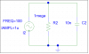
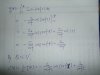
I was trying to derive the voltage of a capacitor from the current i(t)=I0*sin(2τft) through the capacitor, by using Q=CV.
Assume q(t) is the charge on one plate and the capacitor's initial voltage is zero. The following is what I did. Could you please tell me if there's anything wrong with the derivation for the cap voltage?
DSCF0011.JPG
 

Attachments

  • DSCF0011.JPG
    DSCF0011.JPG
    583.4 KB · Views: 337
Last edited:
Hi,

Your math looks right, however there is one slight problem issue. This issue comes up in simulations also where the driving source is a sine source rather than a cosine source.

You will note that the way you have the math set up is that you intend to integrate from 0 to T (upper case T for the 'constant' time and lower case t for the 'variable' time). But you also know that the voltage in a capacitor is 90 degrees out of phase with the current. The problem issue then is at t=0 the current is zero though the cap but the voltage across the cap is also zero, which is not one of the valid steady state solutions (90 degree phase shift) for a sine wave current exciting a capacitor. That means at the start of the integration we have a situation where the capacitor current and voltage do not match the excitation type of waveform we really want, and thus we'll get a result that has a constant term in there too which can not be right because a general sinusoidal current source exciting a capacitor does not generate a DC voltage it will only have an AC component equal in frequency to the excitation.

The sine source excitation thus has a problem when we are looking for steady state solutions because the sine source has an implied unit step built into it. That means instead of integrating just a sinusoidal source we are integrating a sine source plus a DC source, which as you can see from your math, generates a constant DC term which should not be there.

The solution cant be simpler however, all we have to do is use a cosine source instead of a sine source. So we start with:
Io*cos(w*t) instead of Io*sin(w*t) and we get the steady state solution without the constant DC term in there with it. The extra phase shift does not make our calculation inaccurate either because the only phase reference is the driving wave itself.
This is usually the best way to handle these kinds of problems not only in theory but in simulation too and comes up when using inductors also. When the circuit is more complicated however we may have to solve for the driving force phase angle at t=0.

So for your problem:
i(t)=Io*cos(w*t)
dq/dt=Io*cos(w*t)
Integral(dq/dt)=Integral(Io*cos(w*t))
Q=Integral(Io*cos(w*t))
V=Q/C=(1/C)*Integral(Io*cos(w*t))
 
Last edited:
Thank you, MrAl.

The reason I have used a sine current source instead of a cosine one is that I want to see what will happen to a capacitor's voltage at the very beginning when a current starting from zero flows through the cap which has a zero initial voltage. I want to see if the voltage would have a 'transient state', but the math shows that it doesn't. Another weird thing is that it has a constant term which, as you said, shouldn't be there when the transient state dies off, although I think the current does lead the voltage by 90 degrees if
i(t)=Io*sin(w*t) and
v(t)=-(Io/w*c)*cos(w*t)+Io/(w*c)

A cosine current source results in reasonable voltage response and a correct 90 degrees shift in steady state, but I felt I lost something, I felt I couldn't see the nature of a capacitor if I didn't realize what really happens to it at the beginning.

I've considered this problem over and over and I think that my confusion arises because I have set up an impractical condition; if I want to see a capacitor with zero initial voltage exhibit not only steady state response but also its transient state, the starting current flowing through it won't simply be a sine or cosine one. Am I right?
 
Hi,

First, when i say that the voltage is not 90 degrees out of phase with the current at t=0 i mean that the solution is not correct with sin(w*t) at t=0. Let me explain. For a cosine source when the current is zero the voltage is at it's positive peak, and when the current is at it's positive peak the voltage is at zero. For our cap when we start out, the voltage must be at zero because the initial conditions say so. That means that a current that is also zero is not acceptable for a pure sinusoidal wave excitation. Because at t=0 the voltage MUST be zero, we can match the excitation to this condition by simply using a cosine current source, which is at its positive peak when the voltage is zero. This means solutions for ALL t are valid, not just some of the time.
Note that the sinusoidal part of the solution with sin(w*t) can be said to be 90 degrees out of phase, but we cant just say that without also stating that it is always above zero and so it's not really a pure AC signal anymore so a phase difference alone is not descriptive enough anymore, and the charge does not go negative and positive now as it stays always positive which is not the case with the cosine wave excitation.

Incidentally, the solutions using a sine source are never valid at any time for this particular problem. They are not valid at t=0, they are not valid at t=1, nor at t=1000, because there is no transient it's all constant and sine period, so it's just a sine riding on a DC value forever.

Be back in a minute...Ok back, had to run outside for a minute.

The reason for the DC value is because there is no RC time constant that makes up the exponential part. The DC value gradually dies off when we have the e^(-at) part because at large t values that factor goes to zero. With no resistor in the circuit however this wont happen, the DC value will stay there indefinitely. To get rid of it with a resistor you would have to connect a resistor in parallel to the cap, but then that would just complicate the original goal of just simply calculating the voltage from the charge. Still doable if you like though.

So the response with a sine and pure cap will be like a sine riding on a DC value that lasts indefinitely, and the response with a cosine wave is a simple sine wave that goes above and below zero the way simple sine waves do with no DC offset.

It's up to you which way you want to do it, but it seems the cosine way gets rid of the problems and really shows how a cap responds to regular sinusoidal waves in real life without the bother of the DC value. The calculated charge in the cap is then the correct charge for a normal sinusoidal wave.
 
Last edited:
I don't see any major issues with the solution given. This is an initial value problem for a first order system. The capacitor is starting with Q=0 and V=0. Then a current begins to flow at t=0. Steady state solutions are irrelevant here because it is not a steady state problem as given. It's just an integrator. Whatever current you put in, the voltage is proportional to the integral. The initial value of voltage must be specified before integrating, and in this case it is specified to be zero.

The only issue with the solution is that you need to say that v=0 for t<0, and you have given the solution for t>=0.
 
Hello again,

The question asked was about getting the voltage from the charge, so it can be done either way. The cosine excitation makes a cleaner solution and shows what happens in real life when we excite a real cap with a real voltage source after enough time has passed for the transient to die down, but we dont have to wait for the transient to pass to see this.

With the sine source in the theoretical circuit, we'll never see the offset die down because there's nothing to eat up that extra energy. If we do want to see that though, we'd have to add a resistor. So if that's the real goal then that is also valid, but from the wording later it did not sound like that.
 
Actually the question asked if there was anything wrong with the derivation. I see no major issues with the derivation. The particular excitation chosen does not induce a transient because the initial part of a sine wave looks like a ramp, and the integral of the ramp is x^2. But 1-cos(x) looks like x^2, initially. So, the offset cosine solution is perfectly correct and indicates what we would see with a capacitor with insignificant resistance for the current and voltage levels we are interested in.
 
The particular excitation chosen does not induce a transient because the initial part of a sine wave looks like a ramp...
That's what you would think intuitively, but that's not really how it works. That's because the capacitor voltage is zero when the current is zero, and although that is perfectly normal sometimes for a non sinusoidal excitation for a normal sinusoidal excitation after much time has passed it means the voltage is not yet in sync with the current. So what it looks like is that we had a sinusoidal excitation along with a non zero initial condition at t=0. And so the reason for the lack of a transient is only because there is no resistance in the circuit at all, which is also not realistic.

So for a sin(wt) excitation it looks like we had an abrupt change, while for cos(wt) it looks like we had a normal sine wave excitation. That's why i was pushing for cos(wt). If someone wants to analyze with sin(wt) that's ok, but then they will get the very nutty looking response where the voltage sinusoid is riding on a DC offset equal to the peak value of the voltage wave. So instead of seeing a sinusoidal excitation and sinusoidal response, we see a sine source driving a cap that somehow in the past got charged up with a DC current first and never lost that energy because there is nothing to dissipate it (no resistor).

To throw out some numbers, say the current is 1 amp peak and the cap value is 1 farad and the frequency is 1/(2*pi).
If the source current is then cos(wt) we see peaks of +1v and -1v, and the wave looks purely sinusoidal, so we see a sine wave source and sine wave response, which is normal for a cap.
If the source current is then sin(wt), we see the voltage build up to +2v and then down to 0v, and never go through zero. Now although that after all is a response, if we looked at just the waveform we would wonder how a sine wave could cause an unending DC offset in a capacitor. In any real capacitor this would happen too but only for a short time, so we'd see a sine response just like we might expect to see, with no DC offset, because with a non ideal cap we'd have some resistance and the resistance would cause a response with a factor of the form e^(-at) and that's where the transient comes from. It looks like the exponent is -t/RC or similar, but that term will not be found without the resistor (e^0=1).

I hope i've made it clear why i brought this up, but it's interesting to talk about in any case :)
If it still doesnt make sense, try graphing the two responses and try to imagine seeing the sin(wt) response graph and the circuit (one AC current source, one cap) without any other information, and see how strange it looks. We see a cap with a DC offset voltage being driven with an AC source.
 
I think I'm following you somewhat. However, to me the solution is not nutty and I see no problems with a cap having a DC offset being driven with an AC source. Or, at least we can see the DC offset at the beginning of the test, in a regime where the approximations are reasonable.

What I can say is that I agree that the problem is set up as "idealized" because the cap and source are ideal, which means zero resistance in series with the cap and infinite resistance in parallel with the cap. Also, we are assuming infinite bandwidth with a sine wave that can be turned on instantaneously. So, clearly there are approximations. But, we often study idealized cases. Sometimes the result is a paradox if the idealization is too severe, but in this case we get a solution that is representative of what one would see in an experiment, provided that we are looking on the right time scale and at the right voltage and current levels.

One can also solve the more realistic case of a ESR resistance for the cap and a source resistance for the current source. I expect that if you do that, you will see a similar response at the start of the test. Then later in time, the DC offset on the cap will be bled through source resistance.
 
Hi Steve,

Yes, i think that sums it up pretty well :)

I drew my own context from what i thought i knew about the OP's background (e.g. post #3 "weird"), but there's always the chance they want to go totally theoretical sure.
 
No problem Heidi,

I realize I misspoke about a two things before.

First, notice is that if the current source is ideal, then the presence of a series resistance in the capacitor does not really matter. However, if the source resistance is finite, then the capacitor resistance can have an effect, although perhaps it will not be significant in many practical cases.

The second thing relates to the question of whether the DC offset voltage discharges later in time. In the idealized solution, clearly the answer is no, but what if it is not ideal?

To answer this, I show the solution if the source resistance and the cap resistance are included. Let b=1/(Rs+Rc)/C, where Rs is the source resistance, Rc is the cap resistance and C is the capacitance. Then drive the input current as Is=Io sin(wt), where w=2 pi f. We can allow an initial voltage on the cap to be Vo. The solution is as follows.

Vc(t) = Vo exp(-bt) + b Rs Io * ( b sin(wt) - w cos(wt) +w ) / (b^2+w^2) (EDIT: see correction in post # 16)

If we let Vo=0 and take the limit as Rs goes to infinity, we get the solution give in the first post, as follows.

Vc(t) = Io * ( 1 - cos(wt) ) / (w C)

If Vo=0 and if Rs is finite, then we get the following.

Vc(t) = b Rs Io * ( b sin(wt) - w cos(wt) +w ) / (b^2+w^2) (EDIT: see correction in post # 16)

Notice that this also shows a DC offset on voltage that does not discharge in time (EDIT: see correction in post # 16, it does discharge). Hence, I spoke prematurely when I said the charge might dissipate. The relative offset is reduced, but not eliminated.
 
Last edited:
Hello again,

I like to see calculations like this. I do think you should show if the Rs and Rc are each parallel or in series however because the placement makes a huge difference, and we wont know unless you tell us or else we'd have to derive several versions to see which one it is.

Also, if we put one single resistor in parallel to the capacitor, then set R=1, C=1, and w=1, we get:

sine excitation: 2*Vc=sin(t)-cos(t)+e^(-t)
cosine excitation: 2*Vc=sin(t)+cos(t)-e^(-t)

It's now obvious that a short time after t=5 seconds the exponential part becomes very small, and in the limit disappears.
Actually with 16 digit precision the exponential part disappears after about 37 seconds (e^-37=3e-17).
 
Last edited:
So, in my derivation, I made the Rc in series with the capacitor and the Rs is in parallel with the current source. Hence, the idea is to simulate a cap with ESR and a nonideal current source with a parallel resistance. Your solution differs from mine, so I'll have to go back and double check my derivation to see if I made a mistake. I'll report back later.
 
Hi again,

Thanks much for pointing out where the resistors were located exactly. This helps compare results much easier.
I didnt actually check your result yet but here's mine...

With the sine source and Rs=Rc=w=C=I=1 i get:
Vrc=(1/5)*(3*sin(t)-cos(t)+e^(-t/2))

and that is the voltage across the non ideal capacitor, not just the capacitor alone.

I did this kinda quick though so double check this also :)
I can go over it a bit later.
 
OK, when I double check, I see I made a mistake. I now get the following solution.

Vc(t) = Vo exp(-bt) + b Rs Io * ( b sin(wt) - w cos(wt) + w exp(-bt) ) / (b^2+w^2)

Somehow, I dropped that exponential part by accident.

This shows the DC offset eventually decaying in time. This was what my original intuition was telling me. I should have trusted that and looked for the mistake. :)
 
Last edited:
First, notice is that if the current source is ideal, then the presence of a series resistance in the capacitor does not really matter. However, if the source resistance is finite, then the capacitor resistance can have an effect, although perhaps it will not be significant in many practical cases.
Capacitors are driving me crazy when I'm learning the internal capacitances of a MOSFET! I didn't know that a capacitor has resistance! Where does it come from?

For simplicity, I adopt MrAl's circuit version, but I've changed the elements values in order to see the voltage/current variations in a shorter time. I only do the sine excitation.
Current source: 1u*sin(200*pi*t), frequency=100Hz
C=10n F, initial voltage=0
R=1Mega Ω
(connecting the current source to the parallel combination of the resistor and the acp. circuit sketch is missing!)
After some lengthy calculations (I solved the circuit equation in time domain) the cap voltage is
v(t)=0.0247045*sin(200*pi*t)-0.155223*cos(200*pi*t)+0.155223*e^(-100*t)
It matches the simulation.
upload_2014-10-2_22-51-38.png

The upper is the capacitor current-time plot, the bottom is voltage-time.

As you can see, the current flowing through the cap isn't a pure sine wave at the very beginning in time. That's why I said " if I want to see a capacitor with zero initial voltage exhibit not only steady state response but also its transient state, the starting current flowing through it won't simply be a sine or cosine one." in post #3.
And that is why I think I set up an impractical, artificial condition: connecting a sine current source directly to a cap!
 

Attachments

  • upload_2014-10-2_22-28-13.png
    upload_2014-10-2_22-28-13.png
    12.7 KB · Views: 301
Last edited:
I didn't know that a capacitor has resistance! Where does it come from?
You could spend a lot of time studying this question and even very experienced electrical engineers don't know all there is to know about this. But to keep it simple, there is an effective series resistance and parallel resistance created by the dielectric material used. Air gap caps would have less of this effect and vacuum caps almost nothing. Then there is the effective series resistance of the leads/plates which is always present unless you make the cap out of superconducting material, which is not very typical.

For simplicity, I adopt MrAl's circuit version, but I've changed the elements values in order to see the voltage/current variations in a shorter time. I only do the sine excitation.
Current source: 1u*sin(200*pi*t), frequency=100Hz
C=10n F, initial voltage=0
R=1Mega Ω
(connecting the current source to the parallel combination of the resistor and the acp. circuit sketch is missing!)
After some lengthy calculations (I solved the circuit equation in time domain) the cap voltage is
v(t)=0.0247045*sin(200*pi*t)-0.155223*cos(200*pi*t)+0.155223*e^(-100*t)
It matches the simulation.
View attachment 88568
The upper is the capacitor current-time plot, the bottom is voltage-time.
Nice work!


As you can see, the current flowing through the cap isn't a pure sine wave at the very beginning in time. That's why I said " if I want to see a capacitor with zero initial voltage exhibit not only steady state response but also its transient state, the starting current flowing through it won't simply be a sine or cosine one." in post #3.
And that is why I think I set up an impractical, artificial condition: connecting a sine current source directly to a cap!
Personally, I don't think it is impractical or artificial. It's just a case to look at. If you have a poor capacitor and a poor current source, then you will get fast decay of the offset voltage. If you have very good devices, you will see a much longer time before the decay is noticeable. But, yes you have shown that the initial response is not a pure sinusoidal function. It is only pure in the limit as the parallel resistance goes to infinity.
 
Last edited:
Hi again,

I was able to verify Heidi's solution to the specified digits given in her reply, but Steve i was not able to verify your solution in post #16 yet because i wanted to make sure of a couple things.
First, i guess your 'b' is:
b=1/((Rs+Rc)*C1)
is that correct?
Also, i guess you solved for the voltage directly across the (internal ideal) capacitor rather than the voltage that would be seen right at the terminals of the non ideal cap, right?
It already looks right though but i just thought i would make sure what you intended to show :)

And yes Heidi, the circuit with one resistor in parallel to the cap is easier to analyze.
 
Hi MrAl,

Yes you are correct on both questions. That is the correct value of "b", as I defined it. Also, the voltage is derived to be the ideal cap voltage.
 
Status
Not open for further replies.

Latest threads

New Articles From Microcontroller Tips

Back
Top