Group,
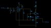
I am having some difficulty with a crazy resonace problem. It’s a simple enough circuit. The transistor Q1 is always on, being biased from a bench top power supply at 0.6V. The FET M1 is switched on and off in a pattern. This pattern may be on for 125ns, off for 125ns and then a delay followed by the same. Its not too important at the moment. When M1 is on, the LED is on. The LED is supplied 8V along a 50cm cable and then there is a cable of length 50cm to transistor Q1. Q1 and M1 are on a PCB and very close together. The lengths of the cable are represented by inductors L1 and L2. I have guessed at their value.
When M1 is switched on, the collector of Q1 begins to resonate at a frequency of 4MHz. It starts off a small sine wave and gets bigger and bigger till it reaches 30V. There is no sign of the resonance at the emitter. The amplitude of the resonance gets worse as you increase the base voltage of Q1 a bit. The LED works but the signal looks horrible. The resonance ends when M1 is switched off.
I assume I have hit some resonance point between the inductance of the cable and the parasitic capacitance by drawing the current through the transistor at this switching rate.
Can anyone give some advice on what is going on
Thanks in advance
Chris