Continue to Site

Welcome to our site!

Electro Tech is an online community (with over 170,000 members) who enjoy talking about and building electronic circuits, projects and gadgets. To participate you need to register. Registration is free. Click here to register now.

  • Welcome to our site! Electro Tech is an online community (with over 170,000 members) who enjoy talking about and building electronic circuits, projects and gadgets. To participate you need to register. Registration is free. Click here to register now.

computer bench supply problem

Status
Not open for further replies.

Hank Fletcher

New Member
Sorry for the newbie question, but I decided to try and modify a computer supply so I could use it as a bench supply. Seemed like a good idea since it didn't cost me anything to get the supply so it seems like a cheap way to get 5V and 12V regulated, and at fairly high currents, too. I searched the net for some ideas on how to do this, and finally followed this guy's notes:
http://web2.murraystate.edu/andy.batts/ps/POWERSUPPLY.HTM
They're pretty good notes and I tried to contact him with my problem below, but I've yet to hear back.

My problem is with the resistor. I used a 10W, 10ohm resistor as is commonly advised, albeit mine is the green, cylindrical wirewound type. It gets really hot, and although I haven't use any heatsink compound the resistor is well ventilated. The supply works for about ten minutes while the resistor gets hotter and hotter, then shuts down. This hasn't fried the resistor yet, which still indicates 10ohms after it's cooled down. Then you can turn the supply on again and watch the whole thing over... but presumably this is eventually going to cook something permanently.

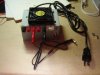
All this said, I did the absolute bare minimum to test the supply and see if it would work as a bench. I didn't open the supply case. I just shorted the green 5V wire to a black ground wire, and soldered the resistor between one of the red 5V wires and another ground wire. For the ten minutes the supply operates, my multimeter gives all the expected voltage readings from each of the supply's lines. Is it just a matter of getting some heatsink compound, or is more current somehow going through the resistor than theory has predicted? Given the likeliness that someone on this forum has done a similar mod I figured I'd take a chance and throw this out there. Thanks!

BTW, my power supply characteristics:
250W Dell (after the year 2000, so wire colours follow industry standards)
5V, 22A
12V, 14A
5VSB, 2A
3.3V, 18A
-12V, !A
 
Last edited:
It may depend on which voltage the PSU monitors for proper operation. In the days of AT supplies it was the +12 line. Usually any small load would make the thing happy - sometimes even a fan.

Your hot resistor is still an iddication that all is not well. It should only be dissipating 2.5 watts, which won't make it more than warm.

I would suggest you lift the green wire you shorted to that black wire. Then, try running the PSU with the resistor connected between +5 and one of the grounds associated with a +5 volt line.

Double check the resistor to be cerrtain it's 10 ohms and not 1 ohm.
 
Search the Internet for the power supply model number, download the datasheet and see what the required minimum is and on which rail to connect it.

Shorting any rail to 0V is never a good idea and is probably what has been causing the problem.
 
j.p.bill said:
It may depend on which voltage the PSU monitors for proper operation. In the days of AT supplies it was the +12 line. Usually any small load would make the thing happy - sometimes even a fan.

Your hot resistor is still an iddication that all is not well. It should only be dissipating 2.5 watts, which won't make it more than warm.

I would suggest you lift the green wire you shorted to that black wire. Then, try running the PSU with the resistor connected between +5 and one of the grounds associated with a +5 volt line.

Double check the resistor to be cerrtain it's 10 ohms and not 1 ohm.
First thing I did was check the resistor... yep, 10 ohms.
I haven't seen anything that suggests the load ought to be on the 12V rail instead, everything I've seen suggested putting the load across the red (5V rail) wire. The supply won't operate without the green wire connected to ground - are you suggesting putting the resistor on the green wire?
 
Hero999 said:
Search the Internet for the power supply model number, download the datasheet and see what the required minimum is and on which rail to connect it.

Shorting any rail to 0V is never a good idea and is probably what has been causing the problem.
I couldn't find the datasheet, but thanks for the suggestion. The supply model is NPS-250GB A, if anyone out there has a knack for finding datasheets!

I was suspicious of shorting the green wire (5VSB) to ground, too, but everything out there on converting supplies tells you to do that. I'm not too sure what alternate approach to take on this...
Thanks.
 
hi hank,

Read thru the web notes re-conversion, the only thing I can see thats different is the 10R 10W, mounting.
As you say the Green wire has to be at 0V to enable the PSU.

The author does stress that the 10R gets VERY hot and must be firmly clamped to the frame and to use heat sink compound.

Its just possible as your 10R is gets really hot its resistance is going up, so at some point its not dumping enough current
to satisfy the switcher???

I would use a car lamp as he suggests [in place of the 10R]

I assume that you have got the fan connected and its cooling the PSU?.

Eric
 
Last edited:
ericgibbs said:
hi hank,

Read thru the web notes re-conversion, the only thing I can see thats different is the 10R 10W, mounting.
As you say the Green wire has to be at 0V to enable the PSU.

The author does stress that the 10R gets VERY hot and must be firmly clamped to the frame and to use heat sink compound.

Its just possible as your 10R is gets really hot its resistance is going up, so at some point its not dumping enough current
to satisfy the switcher???

I would use a car lamp as he suggests [in place of the 10R]

I assume that you have got the fan connected and its cooling the PSU?.

Eric
Hey, thanks! Yes, there's a fan inside the PSU (always was connected - I haven't opened the case and hence haven't tinkered with the PSU's fan), and without any modificatons to the PSU the fan won't turn on. Connect the green wire to ground and the PSU fan turns on, but you can't read any voltages on the red, yellow, or orange wires. However...

I just re-read his notes, too. I got rid of the resistor (disconnected the red and ground wire, put electric tape on the ends). I pulled out some old DC motors (automobile surplus) and a 12V, .35A fan (I'd say it's also from a PSU, but it's a little larger, and louder, than the ones you usually find in a desktop CPU). After plugging in the PSU (fan running, no voltage readings) I tried connectng a motor, the fan, the fan and motor, then disconnecting and reconnecting them to the orange, red, and yellow wires. In all instances... they work! So I guess the PSU I have is one that doesn't get fussy about whether the load is applied before the PSU's plugged in, or after, or anywhere in between. Which is a good thing, right?

I think for the application I'm planning on using the PSU for, I will do as you suggest and try to connect a lamp to the PSU. There's just one more thing I'm curious about though, and that's the different voltage readings I get when I have different loads on the PSU. For instance, with one DC motor connected I might read 11.7V on the yellow wire, but with the fan I might get 11.82V. Is this contrary to what I should expect from a regulated PSU? This difference in voltage is touched upon in that guy's (Andy's?) notes on the mod, but never really explained. Maybe I'm just being a newbie here and not really understanding how a regulated supply works? Anyone want to set me straight?

Thanks very much to everyone who's helping me in this and my other (inadvertent) thread on the subject. Even though I might not have reached the solution directly, all your encouragement and inspiration to continue tinkering is invaluable.
Hank.
 
Last edited:
If you want a cheap power supply check out these. I own the one in the first link (the link is for the new one, but you can get a used one for $4, just browse the rest of the power supply area of the site). The prices are great, and shipping is a fixed $7, even if you buy a few heavy Sealed Lead Batteries.

https://www.allelectronics.com/cgi-bin/item/PS-637/480/5V_8A,_3.3V_4A,_2.5V_2A_POWER_SUPPLY_.html

https://www.allelectronics.com/cgi-bin/item/PS-148/480/POWER_SUPPLY,_5.1V_12A,_12V_2.5A,_-12V_2.5A_.html

https://www.allelectronics.com/cgi-bin/item/PS-337/480/LAMBDA_SWITCHING_POWER_SUPPLY_.html

https://www.allelectronics.com/cgi-bin/item/PS-105/480/POWER_SUPPLY,_5V_8A,_12V_2A,_-12V_2A_.html
 
BTW, I think I originally erroneously diagnosed the reason the PSU automatically shut off. I had blamed the overheating resistor, but I think I was wrong. I think what actually happened was that in the course of tinkering and trying to connect various loads to the PSU that I had accidentally shorted one of the red, yellow, or orange wires to ground. I've done this a couple times now (oops... that's what you get for quick fix tinkering), and the result is always the same - the PSU (I think) detects the short, auto shuts off and forces itself off for about 30 seconds. After that, you can plug in the supply again and everything's back to normal.

To clarify, shorting the green wire to ground does not have this effect. To the contrary, shorting the green to ground is required for the PSU to operate.
 
Ambient said:
If you want a cheap power supply...
Thanks. No doubt the supplies you mentioned are the most practical solution for some people's projects. That being said, I feel obliged to share with those who have read this far to tell them how I got my used PSU for free!

My office is right above the IT department where I work, and knowing about this PSU bench mod and the fact that my school district is constantly going through computer upgrades I thought, "What happens to all the old ones?" I went to inquire, and I offered to buy one of the old PSUs that was taking up shelf space, but due to gov't restrictions on what a public school board can do with old materials they couldn't sell me one. But they could give me one.

Think about it. I get a free PSU. The IT department gets to dispose of a PSU at no cost to them, and it saves them the cost of storing something they'll never use again. It's not cost effective for them to host an auction (which is the only way around the gov't regs) to get rid of the PSU. The PSU doesn't end up in a scrap heap, so we're both doing our part to recycle and save the environment. It's one of those rare win-win-win situations, so I encourage everyone out there to try the same thing. Sure, you might get one of those "no" people, but all you have to do is move on until you find someone who understands the reality of the situation.
 
Hank Fletcher said:
I think I originally erroneously diagnosed the reason the PSU automatically shut off. I had accidentally shorted one of the red, yellow, or orange wires to ground.

Seems I got here too late to help you. I recently rescued an ATX from the junk man. It makes a pretty good psu, but it does easily shut down if it sees the hint of a short circuit.

I used a brake light bulb as the resistor on mine... did a good job while also serving as a on-off indicator and part-time night light. Put it between 12 volt line and ground.

Yep, green wire is your on-off switch. Mine still had all the molex connectors, so I just jumped green to black with a paper clip.

There is an even better how-to tutorial on the net, but I couldn't find it in my bookmarks. Googling for ATX probably will turn it up. That article was accompanied by remarks from several individuals who had in some fashion or another converted the psu to lab use. I found mine especially useful for Op-Amp work, since it has + and - 12 v.

Good luck.

EDIT: Yeah, here's that website: www.wikihow.com/Convert-a-Computer-ATX-Power-Supply-to-a-Lab-Power-Supply
 
Last edited:
Hey Hank,

I converted a computer PSU last month using the same link as AllVol has provided above. Had the same problem..

I also used a green wirewound 10r 10w resistor, I KNOW WHAT YOU MEAN THOSE THINGS GET HOT!!!!!

When you use these high power resistor you MUST secure it to the aluminum chassis of the supply with as much surface area between them - BUT, that is not enough!

My PSU also kept turning off as the resistor heat increased.

Solution:
At least for me;

When using the PSU with no load (except the 10r10w) ensure the resistor is attached at the air vent (right on the perferation holes) so that the fan can alliviate the resistor heat most efficently, also the top of the chassis HAD to be on so as to make the PSU practically air tight inorder to focus all air flow of the fan on to the resistor.

I also taped the hole off which you can see in the last picture of the link provided by AllVol.

Yes computer PSUs are extremely responsive to shorts, thank god. I think my heart stopped when I knowly short mine and the power died :D, but it turned out all good.

PW
 
The resistor value isn't critical and you don't have to load it that much to keep regulation, if you're having trouble with heat just reduce the resistor a bit. I'm using a 20 something ohm resistor because I had one floating around with a more than adequate power handling, works fine. I don't know what methods these ATX power supplies use for short circuit protection but I'm asuming it's a DI/DT trigger. Adding some extra large value capacitors to the output might help if you're suddenly applying a low resistance load to it that you know isn't over it's power rateing.
 
Last edited:
Here is the PSU I made:
 

Attachments

  • PB250024.JPG
    PB250024.JPG
    363.8 KB · Views: 195
Last edited:
Weird, it looks just like mine! ;)
 
A friend of mine worked for a local community college for a few years. He was telling me that they had to incinerate the older computer parts due to gov regs. They were basically trashing perfectly good computers. What a waste. They were not older than 1 or 2 years. They could have been sent off to some needy country but no they gotta be incinerated. Dumb.
 
Hank Fletcher said:
There's just one more thing I'm curious about though, and that's the different voltage readings I get when I have different loads on the PSU. For instance, with one DC motor connected I might read 11.7V on the yellow wire, but with the fan I might get 11.82V. Is this contrary to what I should expect from a regulated PSU? This difference in voltage is touched upon in that guy's (Andy's?) notes on the mod, but never really explained. Maybe I'm just being a newbie here and not really understanding how a regulated supply works? Anyone want to set me straight?

Thanks very much to everyone who's helping me in this and my other (inadvertent) thread on the subject. Even though I might not have reached the solution directly, all your encouragement and inspiration to continue tinkering is invaluable.
Hank.

I converted a 250w atx supply, and I used two 25 watt resistors in parallel(2.5 ohms) on the 5 volt rail. I mounted them on top of the case in a aluminum heat sink with heat sink compound, and at 10 watts the heat sink is just warm to the touch(little kids in the house).

On my atx only the 5 volt rail is regulated , so if you are just using the 12volt rail( like I needed) the more current you pull the more the voltage will drop because it is not regulated.

That is the reason you put a load on the 5 volt( the 12 volt will follow it). Its a compromise,I figured the max current I needed @ 12 volts, and then put that load on the 12volt rail, which dropped below 12 volts. Then I tried different resistors on the 5 volt untill I got back to 12 volts on the 12 volt rail. If you draw higher than your figured current your voltage will drop below 12 volts.

If you power anything with a high inrush of current( like a Nicad battery charger), it will shut down your power suppy even though the power supply maybe rated at a much higher current.I have read that some people were using caps( cant remember what size) on the output of the power supply and that solved the problem and that was mentioned earlier in this thread.
sam
 
Last edited:
You can probably tweak the output from your supply anyway, you just need to find where the feedback loop is and change a resistor value. This could involve a bit of reverse engineering but it's relatively straight forward is you can find the datasheet for the controller IC.

I've always fancied building a switching power supply, one day I might get my hands on an old PC PSU and rebuild it to a variable supply of my specification.
 
Hero999 said:
You can probably tweak the output from your supply anyway, you just need to find where the feedback loop is and change a resistor value. This could involve a bit of reverse engineering but it's relatively straight forward is you can find the datasheet for the controller IC.

I've always fancied building a switching power supply, one day I might get my hands on an old PC PSU and rebuild it to a variable supply of my specification.

It seems there should be a more direct/efficient way of getting what you want out of the power supply, but I dont know enough about them( basically nothing) to do it.
I have seen a couple of people on the web do mods, to get 13.8 volts off the 12 volt, but the way they did it required some extensive gutting.
It just did not seem worth the effort( but maybe they didnt know anything either). sam
 
Status
Not open for further replies.

Latest threads

Back
Top