Hello
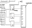
I am running common positive led lights RGB. They require the 12VDC to run on the negative (black) wire going to each light.
In turn when I ground out one of the RGB (wire) lights they light up.
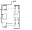
I am using a common negative switch for doing so that I have run through relays.
I have negative wire going through the common of the relay so when it operates the rgb light has source to negative.
Is there a way to do this without the relays?
I am running common positive led lights RGB. They require the 12VDC to run on the negative (black) wire going to each light.
In turn when I ground out one of the RGB (wire) lights they light up.
I am using a common negative switch for doing so that I have run through relays.
I have negative wire going through the common of the relay so when it operates the rgb light has source to negative.
Is there a way to do this without the relays?