GH Crash
Member
I have a problem with a circuit I designed and I need your help in solving it.
First off, I'm definitely in the sub-hacker category when it comes to knowledge of IC and circuit. I can usually put a circuit together once someone gives me the component names and a basic circuit drawing. So, speak to me in small words otherwise you may loose me.
The LIC-P (my designation) circuit is designed to interrupt the current flow from a lithium ion capacitor, LIC or hybrid capacitor, to its load when the capacitor voltage drops to a certain point. Basically the circuit is a voltage detector IC that provides the gate signal to a n-channel MOSFET. The power supply is a LIC of between 10F and 100F capacitance rated for a minimum and max voltages of 2.3 and 4 volts respectively. The load is a small coreless DC motor rated at about 6 watts at 3.7 volts. The LIC-P circuit fits between the capacitor and motor. Attached is the circuit design and data sheets for the tow main components.
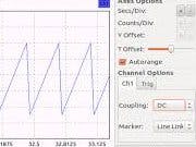
The problem is that the motor rpm varies in a cyclic manner with the circuit in place between the capacitor and the motor. The motor's rpm changes cyclically in a sine wave fashion from max rpm down to about 60% of max. The period of the oscillations is around a second and a half. The motor should run a constant full rpm until the capacitor's voltage drops below the set point of the voltage detector.
1. What is causing the motor rpm oscillations?
2. What do I need to do to the circuit to get the motor to run at a constant RPM consistent with the capacitor's voltage? (I realize that the rpm will gradually decrease as the capacitor's voltage drops.) What other information would be useful to solving this problem.
What other information would be useful to solving this problem?
George


