Electro Tech is an online community (with over 170,000 members) who enjoy talking about and building electronic circuits, projects and gadgets. To participate you need to register. Registration is free. Click here to register now.
Welcome to our site! Electro Tech is an online community (with over 170,000 members) who enjoy talking about and building electronic circuits, projects and gadgets. To participate you need to register. Registration is free. Click here to register now.
The initial complaint was that the sound was at full volume and the volume control had no effect.
That sounded easy, obviously, the gnd connection to the volume control was open.
But, to cut a long story short, when I opened the case and measured the pot, the gnd connection seemed solid, but it may be intermittent due to a dry joint somewhere.
Then I noticed that the audio switching was eratic. It has a Phono, CD, Tuner, Aux & Tape inputs.
So I measured the supply voltages to the audio control & switching ICs - LC7815 & LC4066 ICs and found they are much too high.
They had approx +15 Volt and -15 Volt on their Vdd & Vee pins.
The data sheet for the LC7815 indicates that the max Vdd - Vee is 20 Volt! It's a wonder that they were still working - even though eratically.
I have been tracing the circuit, but it is tedious & time consuming.
So if someone has a circuit diagram, it will save me much time.
sorry..... this began as a duplicate post, because my browser crashed with the edit page open...
sounds like you have bad regulators. these will usually be some TO-220 cased transistors with some zener diodes nearby. the ground on the regulator could be flaky (let me guess? they used the 18ga stranded wire which is wire wrapped to tall posts with a square cross section, to make connections between boards? this was a popular wiring method between about 1970 and 1985.). or the xeners could be bad, or the regulator transistors shorted E-C. dried out electrolytic caps in the regulator can also make it operate in some bizarre ways. normally that would be a good call on the volume control, but once again, what type of wiring method is used. if it's the wrap/posts, you probably have a lot of flaky connections' it's best to remove the wraps, and solder the wires onto the posts the way you normally would if you were building the amp yourself. i have never seen the wire wrap tools that were used for 18ga stranded wire, but they must have been common in Japan because everybody used them.. even if the wrap/post wiring method wasn't used, it's still likely you have one or more bad grounds. i didn't find a CA-65 schematic, but found a CA-30..... switching in the CA-30 was done with real switches, so this is probably not a whole lot like the CA-65... but the regulators for the analog stuff is done with only zeners. if they did it with zeners here, it's likely they continued using that method for a while just a few thoughts, hope something here points you in the right direction
sorry got another thread confused wit his one disregard what i said about the CA-30......
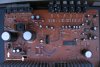
the power transistors in the first picture are your regulators, however, and the small glass diodes are most likely the zeners for them. the most common zener-transistor regulators bias the transistor base with a voltage 0.7 more than the rail voltage required. so a 15V zener on the base would actually give you a 14.3V rail voltage. that can be bumped up 0.7V by putting a forward biased diode in series with the zener. what you Should have on those transistors (approximately), looking at the transistor from the front, 1(B) 15.7V, 2(C) anywhere from 18V on up to whatever the main supply rails are on the big caps, 3(E) 15V. for the negative supply, make all of the voltages negative, but the pinout of the transistor is the same. and yes, they did as i guessed use the awful wire wrap technique....
This site uses cookies to help personalise content, tailor your experience and to keep you logged in if you register.
By continuing to use this site, you are consenting to our use of cookies.

")