Continue to Site

Welcome to our site!

Electro Tech is an online community (with over 170,000 members) who enjoy talking about and building electronic circuits, projects and gadgets. To participate you need to register. Registration is free. Click here to register now.

  • Welcome to our site! Electro Tech is an online community (with over 170,000 members) who enjoy talking about and building electronic circuits, projects and gadgets. To participate you need to register. Registration is free. Click here to register now.

Child's Mini-Pinball Machine

Status
Not open for further replies.

Jettboy

New Member
Hello, mi amigos! Forgive my (temporary) state of newbie-ness, and pleeeeease help me out. I can promise good karma, a heart-felt "thank you!", and maybe a free print if you like surrealist fish art.

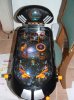
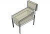
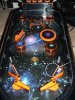
What I'm trying to do, in a nutshell, is gut a child's toy pinball machine and place it in a beautiful, hand-crafted wooden cabinet. Most of the internal circuitry will be unchanged; I'm primarily interested in the asthetic values of the project...creating a cool cabinet with terrific graphics and a hand-painted backglass, etc., but I still want it to work.

I can handle all of the woodwork, glass, paint, mechanics and maybe some of the simple wiring (splicing/soldering wire together for length, moving electronic 'triggers' around, etc.), but I'm almost completely out of my element on everything else. I'd like to add some more lights (including flashing ones), maybe graft in a set of computer speakers, maybe graft in a light-and-siren gizmo from another toy and such, but I don't even know if this sort of stuff is possible.

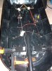
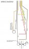
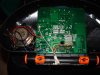
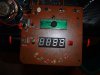
HELP....PLEASE! I'm about to open the toy machine up and start taking pictures of the 'guts', and making some sketches. Any advice you folks could give would be invaluable. Don't hesitate to ask for any reference stuff you need to see or know about.
 
Jettboy said:
I'd like to add some more lights (including flashing ones), maybe graft in a set of computer speakers, maybe graft in a light-and-siren gizmo from another toy and such, but I don't even know if this sort of stuff is possible.

Well, anything is possible;) Is it an older pinball machine? Does it use any micro controllers? Gut it out and take some pictures and post them, that would help.
 
How about brand name/model number to start out. But yeah adding stuff shouldn't be too complicated. It's a metal ball, so a couple of screws, metal strips, or even bare wire could work as a switch. From there its up to you if you want it to do. Suggest you look into timers, like the 555. It's an 8 pin chip with so many uses related to your project, and there is a lot of information on the web availiable, been around a very long tim.
 
I wanted to make a pin ball machine for my A-level design project but the teacher said it was too ambitious and made me make a desk organiser which totally demotiviated me so I got an E.
 
Thanks for the offers of assistance. I have started the gutting process, have taken a bunch of photos and am currently mapping the wiring layout as best as I can. I'll post all of this material as soon as I finish compiling it. Many thanks!
 
OK, here are a few of the photos:
This one is the toy pinball machine AS IS (well, as WAS before I took a screwdriver to it:
whole-tablesample-jpg.13036


This one is a sample of the playing field. Note the circled-in-white metal strip in front of the bumper (a steel spring acts as the bumper). I'm not sure, but does the ball (metal) have to contact both the spring AND the metal strip or...
cu-of-paying-fieldsample-jpg.13039


This one is just a sketch of how the NEW cabinet is going to look. Much like a traditional pinball machine, only a little smaller:
cabinet-sketch-jpg.13037


And this one is the backside of the playing field. The cluster of wiring runs down from the top section (the 'brain' as I've been calling it), where the circuit board and scoring display are, into the bumpers and ball return assembly:
back-of-playing-fieldsample-jpg.13038


And finally, at least for this post, is a diagram I've made of where the wires all attach within the body (backside of the playing field) of the machine:
wiring-diagram-jpg.13040


BUT WAIT! There's more on the way...
 

Attachments

  • whole tableSAMPLE.jpg
    whole tableSAMPLE.jpg
    60.4 KB · Views: 4,263
  • cabinet sketch.jpg
    cabinet sketch.jpg
    24 KB · Views: 3,248
  • back of playing fieldSAMPLE.jpg
    back of playing fieldSAMPLE.jpg
    60.5 KB · Views: 2,966
  • cu of paying fieldSAMPLE.jpg
    cu of paying fieldSAMPLE.jpg
    84 KB · Views: 7,534
  • wiring diagram.jpg
    wiring diagram.jpg
    61.7 KB · Views: 3,624
And, a few more pics. I should mention that this is where everything starts going dim to my lil' pea brain; the circuit board with all of it's attached 'thingies', the LEDS, the power supply (it runs on an AC apapter and wall current), the...well, hell, ALL of the stuff beyond just simple wire stringing and soldering. Unfortunately, I'm afraid this is where most of the modifications I have in mind will probably have to take place.

This is 'the brain' housed in the upper portion (the orange doohicky is a hinge so you can fold the top down for storage):
cu-of-brain-frontsample-jpg.13042


And this one is the backside of the circuit board:
cu-of-brain-backsample-jpg.13041


Is it possible to attach a plug so this guy can run off of just wall current, without the adapter? Can the LEDs be snipped off, soldered onto much longer wires and placed in the play field (under little plastic domes)? Can I add more lights? How would I go about attaching a better speaker, or maybe a SET of speakers? Can the ON/OFF switches be taken off the circuit board and moved elsewhere? Can the scoring display be removed and relocated?

And the really, really, REALLY complex questions...can the sounds and music activated by the targets be changed? Can I attach a small blacklight assembly?
 

Attachments

  • cu of brain, backSAMPLE.jpg
    cu of brain, backSAMPLE.jpg
    43.1 KB · Views: 2,733
  • cu of brain, frontSAMPLE.jpg
    cu of brain, frontSAMPLE.jpg
    38.3 KB · Views: 2,782
Doesn't look too bad at this point.

Guess the ball pushes the spring into the metal strip to make the switch. Thinking it has to hit it hard, rather than just brush up against it.

The two springs in the ball return are most likely another switch, ball completes the circuit.

Might help to get some masking tape and label the wires before you remove anything. Put some on the wire, and some near where it connects, mark them the same.
 
Is it possible to attach a plug so this guy can run off of just wall current, without the adapter?

No, the adaptor converts the 120v AC from the wall to DC and steps it down to a safe voltage. You'll need to keep the adaptor, or atleast an adaptor of some kind.


Can the LEDs be snipped off, soldered onto much longer wires and placed in the play field (under little plastic domes)?

I don't see why not. As long as you can manage the soldering. Might be kinda tedious, but it should work just fine.


Can I add more lights?

I don't see why not, as long as you have a way to trigger them, and to power them. What kind of lights did you have in mind? LEDs?

How would I go about attaching a better speaker, or maybe a SET of speakers?

I'm not sure in this area. Hopfully one of the more audio minded members can advise here. I doubt the board has the brawn to drive more then that little speaker.

Can the ON/OFF switches be taken off the circuit board and moved elsewhere? Can the scoring display be removed and relocated?

Don't see why not, as long as you can get extensions soldered onto the board.

And the really, really, REALLY complex questions...can the sounds and music activated by the targets be changed? Can I attach a small blacklight assembly?

This is also past my scope of knowledge. I know it could be done, but i'm not sure how hard it would be. I know some surplus electronic sites sell record/playback modules, mabey you cold use somthing like that for each sound/target. Not the best way to do it i'm sure, but it might be the simplist.
 
Status
Not open for further replies.

Latest threads

New Articles From Microcontroller Tips

Back
Top