Continue to Site

Welcome to our site!

Electro Tech is an online community (with over 170,000 members) who enjoy talking about and building electronic circuits, projects and gadgets. To participate you need to register. Registration is free. Click here to register now.

  • Welcome to our site! Electro Tech is an online community (with over 170,000 members) who enjoy talking about and building electronic circuits, projects and gadgets. To participate you need to register. Registration is free. Click here to register now.

Charging a protected Li-Ion cell?

Status
Not open for further replies.

Veraxis

Active Member
Hello all,
I recently bought a set of protected 18650 cells (I bought them here: https://www.amazon.com/gp/product/B00O8U187W. They are say they are based on the specifications of the unprotected cell found here: https://www.tme.eu/en/Document/40f2659afab69dbec94c09cc473a0e25/ICR18650-26F.pdf.) Seeing them in person, they appear of good packaging and quality and do appear to have the proper protection IC and gas vents, so I have no reason to believe that they are among the many Chinese knockoffs that are everywhere on the internet. I may perform tests later if deemed necessary.

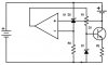
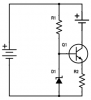
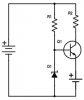
More to the point, the protection circuit in each cell supposedly protects against over-charging/over-current, so does this mean that I can use a simpler charging circuit, rather than the more complex charging scheme for unprotected cells? (see: **broken link removed**). For example a simple constant-current or constant voltage circuit using a transistor? (see schematics). or would it still be advisable to have some kind of feedback mechanism to stop the charging once a certain charge voltage has been reached? (see other schematic).

At a more basic level, if the cell is protected, is it safe to rely on that circuitry to stop the charging once the cell is fully charged, or should I still be using a full multi-staged charging scheme as would be necessary for an unprotected cell? Are "protected" cells meant to effectively have the charging circuitry built-in, or is this merely a failsafe for worst-case-scenario failure of the charging hardware? I have relatively little experience with rechargeable batteries, so any advice you could provide would be appreciated.
 

Attachments

  • constant current with feedback.png
    constant current with feedback.png
    10.1 KB · Views: 256
  • constant current.png
    constant current.png
    6.2 KB · Views: 231
  • constant voltage.png
    constant voltage.png
    6 KB · Views: 264
Last edited:
The expensive no-name-brand batteries have almost no spec's for the "protection circuit". Amazon knows nothing about electronics, why didn't you buy name-brand batteries from a real electronics parts supplier??
A Chinese company sells a photo of a protection circuit to battery manufacturers who are not name-brand and it looks identical to the real circuit. Some Chinese 18650 Lithium batteries are fakes and are full of flour.

If a protection circuit could be used as a charger circuit then it would be called a charger, wouldn't it? No, it is just a fail-safe protection circuit. It limits the voltage and current.
A lithium charger limits the voltage to 4.20V per cell. The protection circuit also limits the voltage to 4.20V if the charger is defective.
The charger circuit limits the charging current but without specs we do not know if the protection circuit does and we do not know how much.
The charger circuit detects a full charge (by measuring the current, not the voltage), then shuts off to prevent over-charging but a protection circuit will not shut off the charging current. When the charging battery voltage reaches 4.20V then the battery is only about 70% fully charged. Lots of charging must continue until the charging current drops to a certain percentage of the normal charging current, then shut off.
Most people use a battery charger IC made to charge a Lithium cell.
 
Some reviews of the no-name-brand battery says it is too big to fit in his charger. I think the protection circuit on (or its photo) one end makes it longer.
 
Thank you for the information. I am aware that these protection circuits add to the length of the batteries. This is apparently the case for all protected cells that I have seen. According to my measurements, it adds an additional 3-4mm to the 65mm bare cell, which is fine for my application. If I were to use the constant current design listed above using the feedback mechanism shown using a 4.2V reference voltage, would that be sufficient? I would probably use a charging current of roughly 1.2A.

For reference, someone did tests on this manufacturer's batteries: https://www.candlepowerforums.com/vb/showthread.php?398641-Test-Review-of-Foxnovo-18650-3100mAh-%28Blue-white%29 (this is for their 3100 mAh battery rather than the 2600 mAh version). According to this, the protection circuit works just fine and they have roughly their rated capacity. As I stated, I am well aware of the fakes that are sold online, but I see no reason to believe that these are illegitimate as of yet. Foxnovo is apparently a maker of battery chargers.

Alternatively, do you have a preferred source for purchasing batteries?
 
Last edited:
I think you should use a battery charger IC. It has temperature sensing in case the battery is damaged which causes a fire and the IC also refuses to set a battery on fire that has its voltage too low.

I salvaged some pretty old name-brand 18650 unprotected Li-Ion cells from a laptop computer and a portable DVD player and they work fine. I charge them from an LM317 4.20V regulator and the current is limited by the wall-wart power supply that feeds it.
I let it charge for a few hours then I disconnect the cell.

I buy Li-Po batteries assembled in the US and others that are made for and sold only by a US company. I buy US alkaline and Ni-MH batteries from whichever home supplies store who has them on sale. Recently I bought some Energizer Ni-MH cells from Target because they are liquidating everything at very good prices since they are leaving Canada.
 
After a some time, I took AG's suggestion and found some old junker laptop batteries at a tech dump, where I was able to salvage a few good unprotected 2400 mAh cells for testing. I then modeled a simple charging circuit and am currently testing a physical prototype (see attached schematics). I ran two simulations for current into the battery versus a voltage sweep of V2: one for zero series resistance on the cell and another for a 0.5-ohm series resistance with the battery cell (see attached graphs). from what I can tell, the simulations predicted that the current would drop to zero pretty much exactly as the voltage reached 4.2V, which is what I wanted.

I am currently testing a breadboard prototype of the circuit. R1 has been set so that the voltage between V+ and the non-inverting input of the op-amp is 4.1V (I would do 4.2V, but I am playing it safe for testing in case of any input offset on the op-amp), and R2 has been set so that the collector current of Q1 is 1A when the cell at V2 is replaced with a short (or, in this case, an ammeter for setting the current). As I type this, the first set of cells is almost finished charging, and the charging current has dropped to about 200 mA, and the cell voltage directly at the contacts is about 3.95V (so I would estimate that the alligator cables I am using to connect to the battery tabs have a series resistance of about 0.75 ohms). the heatsink for Q1 got pretty warm during the initial charging at 1A, but that seems pretty reasonable here.

What do you all think? Is this a safe charging circuit as it is or would you add additional improvements? The power supply rails will be from a 9V 7809 regulator, and will be set using trimmer potentiometers, which I will then glue down. I thought that this 9V circuit with a feedback mechanism might be preferable over simply relying on the built-in current limiting in an LM317 as suggested by AG, as it allows me to manually set my charging current using the R2 trimmer.

charger 2.jpg no series resistance.jpg 0R5 ohm series.jpg
 
The circuit should work, but there are a few potential issues.

You are using the main regulator as the voltage reference. That will be get the largest voltage drops due to resistance in the wires etc. A separate regulator for the voltage reference would be neater, but it would have to be referenced to the positive side of the cell being charged. There is no need to regulate the main supply, as long as the op-amp and the heatsink on Q1 can take the largest unregulated voltage.

The potentiometers have no resistors at the top and bottom. R1 can be used to adjust over any voltage between 0 and 9 V, when you will only want 4 - 4.5 or so. If you put a 33 k resistor in series with both ends, you would get a range of 4 - 5 V or so. You could juggle the values a bit and put a slightly larger resistor at the bottom end if you wanted. With the 33k resistors, you will turn the resistor 7 times as much to make a voltage change, so it will be much easier to give fine adjustments.

You could similarly adjust R2 with a 6.8 k or so between it and the op-amp. That will reduce the upper range of the current limit and give somewhat easier adjustment. There is no harm having adjustment that goes to zero so there is a definite downside to putting a resistor in series with the other end of the R2. The upper limit on the current is given by R3, and is about 1.3 A, at which point the base of the darlington is at about 5.7 V. A 6.8 k resistor would keep the current a bit below that.

You should have a stabiliser capacitor between the output and the inverting input of the op-amp to stop high frequency oscillation. Also you should put a resistor the wire between the battery and the inverting input, so that the capacitor dominates at high frequencies. In this context, high frequency is anything above 1 Hz or so, but you should try to reduce the gain above 1 kHz or less.

Finally, you should have a resistor between the non-inverting input and positive. That is there so that if the wiper of R1 doesn't make contact, charging will stop, rather than doing something unpredictable, like overcharging the battery. The value of that resistor will affect the voltage range slightly, and something like 1 M should be fine, but I haven't done the calculations.

charger-2.jpg
 
Last edited:
Hi,

You can make pretty nice Li-ion chargers out of an LM317. This makes it much simpler, and you can add current control with a simple small transistor like a 2N2222 and sense resistor.

Yes it is better to use a circuit rather than depend on the protection circuit for charging.
 
All Lithium battery charger ICs have a current sensor that disconnects the charging when the current drops to about 1/40th of the mAh rating of the battery because it is bad to overcharge a lithium battery. The charging current drops low but not to zero.
 
Also, proper Li-Ion chargers will slow the charge to about C/10 while the battery voltage is below the normal charging range.
Correct. A Lithium battery cell with its voltage lower than about 3.0V is dangerous when charged and might catch on fire if its charging current is as high as for a cell with a normal voltage. Many Lithium cell chargers actually refuse to charge a cell with a voltage too low.

If you do not use a proper Lithium battery charger IC then post a video of your home burning down. I am not kidding. Lithium (and Magnesium used in white hot flares, Titanium also burns very hot) are VERY active metals.
 
Thanks for all your input, guys. Just so we are all clear, my goal here is to design a charging circuit so that I can learn about working with lithium batteries. If all I wanted to do was charge some batteries, I would have just bought a battery charger.

I am well aware of the dangers of working with lithium batteries. I am taking the necessary precautions during testing to ensure that the supply I use is current limited and that I never leave the circuit unattended while charging. I checked the cell voltages when I salvaged them and ensured that none of them had been discharged past their rated discharge of 2.7V. I also checked that none of the batteries were getting hot while charging (they did not). The batteries will be used with a protection circuit that prevents the cell voltage from dropping below their rated range, so hopefully I will not have to charge batteries that have been over-discharged, otherwise I plan to charge them manually from a controlled bench supply if this happens.

Given the improvements suggested by others, it seems that I may need to switch over to a more complex digital control circuit that accounts for different cell voltages and the charge current. Probably something with a microcontroller will be easiest. It will probably be easiest to read the current using the voltage at the R3 resistor and use hysteresis to shut off the charging current then reset the circuit once the cell voltage drops below a certain point (maybe 3.9V or so). I'll post back once I have something. (or if my house burns down, I guess! :p)

Also, as a final note...
...If you do not use a proper Lithium battery charger IC then post a video of your home burning down. I am not kidding.

...I charge them from an LM317 4.20V regulator and the current is limited by the wall-wart power supply that feeds it. I let it charge for a few hours then I disconnect the cell.

So tell me... does your LM317 charger digitally shut off the charging current below 1/40 C and run at reduced current when the cell voltage is below 3V? If so, feel free to post the schematics. If not, I guess I should look forward to your video as well! ;)

In all seriousness, though, I will be careful, and I do appreciate your advice, AG.
 
Last edited:
Ive used the LM317 Approach to charging, but Ive charged LiFePO4 batteries with it. I was paranoid (even though that type of chemistry isnt as violent as lithium ion) and kept checking voltage and current every few minutes. A data logger would have been ideal in this situation. When the battery was charged, it was at 3.6v with less than 1mA flowing to the battery. I have tried to use a small 8 Pin PIC to control the charger when it reaches that point, but my efforts have proved fruitless.

https://shdesigns.org/lionchg.shtml

Is the one I built. Design 3 has a LED that indicates charging. I used R1 to check the charge current, and from there its simple Ohms law. Obviously you can make a few improvements, I used a LDO instead of a LM317.

Microchip has charging IC's for very cheap and a charger board can be built for $1-$2. When ever I use my own chargers I still am paranoid, I always set the battery on something fireproof or near a bucket of sand, just in case (outside would be better). Murphy's law. However, I do find that since I am limited by the amount of heat the charging IC can dissipate, the charging current is usually limited to 200mA or less.
 
my goal here is to design a charging circuit so that I can learn about working with lithium batteries.
Why re-invent the wheel? Simply learn about and copy the circuit in a battery charger IC. At www.batteryuniversity.com they have details about charging and discharging all types of batteries.

So tell me... does your LM317 charger digitally shut off the charging current below 1/40 C and run at reduced current when the cell voltage is below 3V?
My LM317 is a simple 8.40V voltage regulator that charges two 18650 cells in series without a balancing circuit. The 9VDC unregulated wall-wart that powers it limits the current to about 0.5A. Nothing disconnects the battery when it is charged but I do the next morning. The battery is used in a portable hand-held vacuum cleaner and the battery is charged whenever the motor runs too slow.
 
Status
Not open for further replies.

Latest threads

Back
Top