Continue to Site

Welcome to our site!

Electro Tech is an online community (with over 170,000 members) who enjoy talking about and building electronic circuits, projects and gadgets. To participate you need to register. Registration is free. Click here to register now.

  • Welcome to our site! Electro Tech is an online community (with over 170,000 members) who enjoy talking about and building electronic circuits, projects and gadgets. To participate you need to register. Registration is free. Click here to register now.

Changing speaker impedance.

Status
Not open for further replies.

Nigel Goodwin

Super Moderator
Most Helpful Member
I thought I'd throw this open for opinions?.

I've been given a pair of Celestion PA speakers, with duff bass units. The only problem is that they are 4 ohm, and 8 ohm would be much better for me! (and I can get some 8 ohm Celestion bass units at a decent price that will drop straight in).

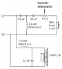
I'm attaching the circuit of the crossover below, now what I want to know is if I replace the bass unit with an 8 ohm one (and change L2 and C3 accordingly), could I just change R1 to 6.2 ohm and keep the respective levels between HF and LF the same?.
 

Attachments

  • crossover.gif
    crossover.gif
    2.2 KB · Views: 1,288
The information contained between the following brackets represents my knowledge of simulators { }. With that said, I'd wonder if you couldn't model this in a simulator. I do realise that the behavior of the speakers is somewhat dependent on the enclosure however you might ignore that to see what the simulator tells you. I had thought about doing the math by hand but just thought about it .....
 
If you nearly triple the value of R1 then the tweeter's output will be too low. You need a reduction of only 3dB.

Don't simply increase R1 to increase the attenuation of the tweeter. Then the tweeter will have a peak in its response near the crossover frequency.

Instead, make a 2-resistors voltage divider attenuator having the same effective source resistance as the original 2.2 ohms, but with 3dB more loss.
Or you could completely redesign the tweeter's crossover circuit to use a higher source resistance.
 
stevez said:
The information contained between the following brackets represents my knowledge of simulators { }. With that said, I'd wonder if you couldn't model this in a simulator. I do realise that the behavior of the speakers is somewhat dependent on the enclosure however you might ignore that to see what the simulator tells you. I had thought about doing the math by hand but just thought about it .....

The information contained between the following brackets represents my knowledge of simulators {.} :lol:

I'm not sure if this is a dig about my opinion of simulators or not?, but it's probably not a bad situation for one, because it's a very simple circuit.

Perhaps I ought to dig back through all the posts and see what's free that people recommend :lol:
 
audioguru said:
If you nearly triple the value of R1 then the tweeter's output will be too low. You need a reduction of only 3dB.

It's not so much the level I'm concerned about, it's the impedance, the speakers are rated at 250W 4 ohms, my PA amp will put 200W in 8 ohms, and 400W in 4 ohms. The existing 2.2 ohm feeding the tweeter crossover will drop very little, adding an extra 4 ohms will make the total impedance around 8 ohms (assuming the original was around 4 ohms).

Don't simply increase R1 to increase the attenuation of the tweeter. Then the tweeter will have a peak in its response near the crossover frequency.

I'm not very clear on that?.

Instead, make a 2-resistors voltage divider attenuator having the same effective source resistance as the original 2.2 ohms, but with 3dB more loss.
Or you could completely redesign the tweeter's crossover circuit to use a higher source resistance.

I can see I'll have to play with a simulator 8)
 
Nigel - not a dig about your knowledge at all. I know plenty about computer modelling just not about circuit simulators. On the surface it would seem to be a fairly basic task for a simulator - audio frequencies and passive components.

I do share the same worries you and others have expressed about heavy reliance on a simulator -as a substitute for basic understanding. I recall attending a very expensive week long class for a fairly expensive software package (HVAC design/simulation). While anyone could attend the instructors preached constantly that the software was a tool for skilled professionals and not a substitute for a solid base of knowledge. They did that because a number of students were clearly poorly qualified but they were successful at generating lots of numbers and wonderful looking reports. The last day included a number of real problems and as you might guess - everyone produced output that looked great - only some got the right answer - those who didn't just didn't understand the basics. The real concern was that the various employers need the right answers, not just reports.
 
Nigel Goodwin said:
audioguru said:
Don't simply increase R1 to increase the attenuation of the tweeter. Then the tweeter will have a peak in its response near the crossover frequency.

I'm not very clear on that?.

C1 and L1 resonate and cause a higher signal across L1 which feeds the tweeter. The resonance of C1 and L1 boosts the response just enough when the source and load resistances are correct to result in a flat Butterworth response.
 
audioguru said:
Nigel Goodwin said:
audioguru said:
Don't simply increase R1 to increase the attenuation of the tweeter. Then the tweeter will have a peak in its response near the crossover frequency.

I'm not very clear on that?.

C1 and L1 resonate and cause a higher signal across L1 which feeds the tweeter. The resonance of C1 and L1 boosts the response just enough when the source and load resistances are correct to result in a flat Butterworth response.

Thanks, I might try measuring it (and perhaps simulating it as well), and see what the outcome is. I really don't want to have to replace the 4 ohm tweeters as well as the bass units, they cost too much :lol:
 
Hi Nigel,
Instead of replacing the tweeters with 8 ohm ones, connect the 2.2 ohm resistors directly in series with them and design a 6.2 ohm crossover. You're going to replace the woofer's crossover parts to match its 8 ohms anyway. :lol:
 

Attachments

  • crossover_984.gif
    crossover_984.gif
    3.4 KB · Views: 887
2.2K?

for lower volume, yes.

but I suggest replacing it with a 4 ohm resistor.

4 ohm speaker + 4 ohm resistor = 8 ohms. or use the appropiate inductor as a replacement.

since the other speaker is already 8 ohms, no extra resistance is required.

I personally go for balance here.
 
MStechca,
Replacing the 4 ohm woofer with an 8 ohm woofer results in half the power, which is a loss of 3dB.
If you put a 4 ohm resistor in series with the 4 ohm tweeter then both the voltage and the current is halved, resulting in a loss of 6dB.

The 2.2 ohm resistor in series with a 5.31 ohm tweeter would result in a loss of exactly 3dB. Since the tweeter has inductance and since it is crossed-over at a frequency higher than its minimum 4 ohm rating, then it most likely is close to 5.31 ohms at the crossover frequency.

Quality speakers use a series capacitor and resistor across the speaker drivers to cancel the inductive rise of their impedance with higher frequencies, and the resulting known impedance is used when calculating parts for the crossover.
 
audioguru said:
Nigel Goodwin said:
audioguru said:
Don't simply increase R1 to increase the attenuation of the tweeter. Then the tweeter will have a peak in its response near the crossover frequency.

I'm not very clear on that?.

C1 and L1 resonate and cause a higher signal across L1 which feeds the tweeter. The resonance of C1 and L1 boosts the response just enough when the source and load resistances are correct to result in a flat Butterworth response.

OK, I've had a play with a sinewave generator and a scope!, the crossover frequency actually measures around 3KHz. I've tried adding a 3.9 ohm in series with the existing 2.2 ohm, and it doesn't seem to cause any problems?, the crossover is still at the same frequency, and there doesn't seem to be any ill effects as I slowly sweep the frequency, it looks just the same as before (except smaller of course).

So for an initial try I'll just get a pair of 8 ohm bass units, alter the bass crossover, and change the 2.2 ohm for a 6.2 ohm, and see how they sound.

Bear in mind it's for PA, not HiFi, so a flat response isn't a great requirement.
 
Hi Nigel,
I'm a perfectionist. There are two ways to do anything, the correct way and the "other" way.

The original crossover had its tweeter attenuator resistor ahead of the filter which ruins the Q of the filter. The tweeter attenuator should have been after the filter then calculated for the series impedance. An L-pad (resistive divider) could have been used to adjust the tweeter level without changing the crossover parts.

This crossover circuit is common:
 

Attachments

  • speaker_crossover.png
    speaker_crossover.png
    5.5 KB · Views: 816
audioguru said:
Hi Nigel,
I'm a perfectionist. There are two ways to do anything, the correct way and the "other" way.

The original crossover had its tweeter attenuator resistor ahead of the filter which ruins the Q of the filter. The tweeter attenuator should have been after the filter then calculated for the series impedance. An L-pad (resistive divider) could have been used to adjust the tweeter level without changing the crossover parts.

This crossover circuit is common:

Have a look at , which is a Celestion design for a very similar 8 ohm PA cabinet, and it has a 10 ohm series resistor before the filter 8)
 
Yeah, Celestion are good guys. They must have had a good reason to do it their "other" way.

I don't like the polyswitch: "Where did the tweet go? It worked a minute ago. Replace this intermittent speaker."
I don't like the core in the woofer's inductor. I like woofers to give the full impact of drums without a core saturating. :lol:
 
audioguru said:
Yeah, Celestion are good guys. They must have had a good reason to do it their "other" way.

Yes, Celestion are one of the good speaker manufacturers, but like anything else, it's all cost driven.

I don't like the polyswitch: "Where did the tweet go? It worked a minute ago. Replace this intermittent speaker."

Mine has them as well, it's so they can advertise the speakers as having 'internal protection' :lol:

I don't like the core in the woofer's inductor. I like woofers to give the full impact of drums without a core saturating. :lol:

It's common in PA speakers, mostly for cost reasons, but PA speakers certainly give plenty of bass! - it's not like puny little HiFi speakers, you've got big drivers and big cabinets, you can pump plenty of air :lol:
 
OK, everyone take a deep breath!.

I've downloaded SwitcherCAD III so I can try simulating the crossover!.

So I've been having a play (I've also measured the values of the inductors in the existing crossover, as I realised one of my multimeters has an inductance range - that I've never had occasion to use before!), the bass inductor reads about 0.6mH (presumably 0.64mH?) and the treble inductor reads about 0.08mH.

I used the simulator to plot the outputs of the crossover into simple resistive loads, with the original values. I then changed the bass unit to 8 ohms, doubled the value of the inductor, and halved the value of the capacitor, and ran the simulation again - the plot was essentially identical (as expected).

I then tried changing the 2.2 ohm feeding the treble filter to 6.2 ohms, and ran it again, as expected the level dropped somewhat, but the filter function didn't change appreciably - so I'll probably try it like that and see what they sound like.

In both cases the tweeter shows a large peak around 200Hz, presumably this is partly due to using resistive loads, rather than actual speakers?, I couldn't see any speaker components in SwitcherCAD III - not that I really knew how to use it :lol:
 
audioguru said:
Hi Nigel,
I'm a perfectionist.
In electronics, to me, I could say that. For everything else, I can't tell how "Perfect" you are. :lol: :lol:

There are two ways to do anything, the correct way and the "other" way.
The wrong way that is.

I don't get it. Why should a speaker circuit be so complex?

The simplest one would be a speaker and a coupling capacitor (1uF+) in series. Couldn't a speaker have inductance and be used as part of a filter?
you could connect a capacitor across it.

Just my 2 cents.
 
Hi Nigel,
My speaker and crossover design software is on the broken hard drive of my old computer. The shareware programs I used are now pay-per-use.

But I recall that in a Butterworth 3rd-order highpass filter for a tweeter, the capacitor's value to the tweeter is a little more than 3 times the value of the one from the amp. In your crossover the capacitor values are equal so I don't know what the response would be.

Sure, try it by just changing the attenuator resistor. :lol:
 
audioguru said:
But I recall that in a Butterworth 3rd-order highpass filter for a tweeter, the capacitor's value to the tweeter is a little more than 3 times the value of the one from the amp. In your crossover the capacitor values are equal so I don't know what the response would be.

Funny you should say that!.

The Celestion link I posted uses 3uF and 8uF (at 8 ohms), yet the one in the Celestion cabinet I have here uses two 4.7uF (at 4 ohms) - presumably it's down to the actual tweeter used?.

I wonder if the final values were arrived at with acoustic tests, rather than calculations?.
 
Status
Not open for further replies.

Latest threads

New Articles From Microcontroller Tips

Back
Top