Continue to Site

Welcome to our site!

Electro Tech is an online community (with over 170,000 members) who enjoy talking about and building electronic circuits, projects and gadgets. To participate you need to register. Registration is free. Click here to register now.

  • Welcome to our site! Electro Tech is an online community (with over 170,000 members) who enjoy talking about and building electronic circuits, projects and gadgets. To participate you need to register. Registration is free. Click here to register now.

CD4060 emulation problem

Status
Not open for further replies.

alec_t

Well-Known Member
Most Helpful Member
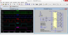
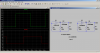
Not having an adequate CD4060 spice model I tried emulating a 4060 by following the CD4060 datasheet schematic and bolting on a couple of gates to a 4020 model in the CD4000.lib library downloaded from the Yahoo LTspice user group. The added gates are configured as a clock oscillator as per the datasheet. The Q4 output of the 4020 should be pulsing at 1/16 the clock rate but, for some strange reason, is variably at 1/5 or 1/6 the clock rate. Any thoughts on why? On its own, when clocked by a normal PULSE voltage source, the 4020 model seems to behave itself.
4060-emulation.gif
 

Attachments

  • 4060_emulation.asc
    967 bytes · Views: 306
hi alec,
Down loaded your asc, will run it later, see how we compare.

For reference this is a 4060 zip I did some time ago, it may help.
E
 

Attachments

  • eg_4060.zip
    2.5 KB · Views: 323
hi,
IMO its a timing problem in the CD4xxx models.
When we add an extra inverter U4 between the pulse gen and the 4020 CLK, we get the same problem.

If the SPEED of U4 is changed from 1.0 to 2.0 , the 4020 divides correctly.

Using a Voltage source for the CLK, set at 50Hz, the 4020 also works correctly

E
 

Attachments

  • AAesp04.gif
    AAesp04.gif
    46.8 KB · Views: 1,357
Thanks Eric. I was confident you'd have the answer!
I notice, too, that the Q1 output shows a glitch, and presumably that glitch is responsible for errors in subsequent stages.
Have downloaded your zip. I'm surprised, given the CD4060's popularity, that there isn't an 'official' Spice model for it available anywhere on the web (at least, none that I could find).
Playing with your sim, I idly tinkered with the TRIPDT value of the components; but that doesn't cure the problem. I see the problem is there when using the CD4024, too; so as you say it looks like a timing issue with all the CD4xxx family. Bummer. Anyone not aware of it will get dubious sim results.
I found the SPEED value of 2.0, for the gate which drives the Clk input of the 4020/4024, can be reduced to 1.5 and still cure the Q1 glitch while reducing the sim run-rate slightly.

Edit: It gets curiouser and curiouser (as Alice would say). Further play shows the SPEED =2 value doesn't always cure the problem, and that the SPEED can be left as 1.0 provided the timing cap (Tc) value is small (<~20n is ok, >~20n is not). I'm thinking the capacitive load on the Clk input of the 4020/4024 is the culprit. Using a voltage source for the clocking, or adding a series resistor (value dependent on the timing cap) between Tc and the Clk input fixes things, but the problem persists if a CMOS buffer (CD4050) between Tc and Clk is used!
 
Last edited:
I modeled the CD4060 from the TI datasheet about a year ago, but it takes a while to simulate.

I interrupted the simulation.
Have a look.

eT
 

Attachments

  • CD4060B.png
    CD4060B.png
    178.9 KB · Views: 775
Thanks, eTech.
Yet more play and I think I've sussed the cause of the problem; it's the oscillator.
Here's a sim showing the conventional RC oscillator configuration as per the 4060 datasheet. If the 4060's NAND gate is modelled as a 4011 there is ringing present on the leading and trailing edges of the oscillator output pulse (out1). If instead a 4093 is the model then the ringing is absent (out2), albeit the oscillator period is greater.
Spurious-pulses.gif
 

Attachments

  • Spurious pulses.asc
    1.4 KB · Views: 255
Last edited:
hi Alec_t

Its been about a year, but I believe I ran into the same problem. I couldn't really use any of the cd4000.lib sub circuits when modeling the part. I basically had to roll my own sub circuits....two inverter oscillator with a "two phase clock" output to drive the ripple counter. I used A devices for the two inverter oscillator and built the ripple counter (with TGates) from the data sheet.

eT
 
Hi eTech. I was hoping to be able to make use of a CD4020 in the 4060 emulation, rather than build things from T-gates. I've just found that applying Eric's 'SPEED = 2.0' trick to the NAND gate (4011 is ok, 4093 not necessary) rather than to the inverter gate gets rid of the spurious ringing on the leading and trailing edges of the clock pulses (at least, for the range of Ct I've tried so far), so it looks promising.
 
hi again.

I just ran your sim...I didn't see any ringing...

Also, set initial conditions to help the oscillator startup...added labels A and B, then added ".IC V(A)=0 V(B)=0" to the schematic,
and removed .uic from the tran statement.

eT
 

Attachments

  • OSCNoRing.png
    OSCNoRing.png
    46.4 KB · Views: 457
The ringing is there if you zoom right in on a pulse edge. There's an extra oscillation of ~180nS width.
 
Hi eTech. I was hoping to be able to make use of a CD4020 in the 4060 emulation, rather than build things from T-gates. I've just found that applying Eric's 'SPEED = 2.0' trick to the NAND gate (4011 is ok, 4093 not necessary) rather than to the inverter gate gets rid of the spurious ringing on the leading and trailing edges of the clock pulses (at least, for the range of Ct I've tried so far), so it looks promising.

:p I guess I wasn't clear...I didn't just use Tgates....but built the ripple counter from the schematic on the datasheet which also includes Tgates. Anyway, good luck.

Yeah...I think the speed parameter actually is changing prop delay of the device. The issue might be related to TD being exactly the same for both devices.

eT
 
Last edited:
So do I on the 4011.
 

Attachments

  • AAesp06.gif
    AAesp06.gif
    22 KB · Views: 373
  • AAesp07.gif
    AAesp07.gif
    20.7 KB · Views: 384
Were you using Speed=2 for the 4011 Eric? I found that got rid of the wigglies. With Speed=1 they're present.

Edit: I spoke too soon. Increasing Ct to 10uF saw the return of the wigglies :(. So I brought in the big guns and bestowed Speed=5 on the 4011. That got rid of them. Still no sign of them with Ct=100uF. Is anyone likely to try a cap value greater than that? I'm not sure how far we can go with increasing the Speed value ;).
 
Last edited:
Hi alec

The TI datasheet (pg 3-161) has RC Operation data. If I understand what is says, Cx can be as high as 1000 uF with a 5v supply. :eek:

eT
 
That's interesting. And the Fairchild datasheet recommends not using the RC oscillator at supply voltages < 7.0V if Rt <50k. Makes me wonder if there could actually be some timing gotcha in the real IC, and the sim model is accurately reflecting this? :).

Update: With Ct= 1000uF, Rt=10k and Speed=5 for the 4011 the sim clock pulses are free of ringing.
I'm not a fan of the 'RC differentiator' oscillator configuration as per the datasheet, since it drives the NAND input beyond the supply rail voltages (albeit with current limited by a resistor). My preference is to use an 'RC integrator' configuration with the right-hand end of Ct being grounded and the two gates having a feedback resistor to form a Schmitt trigger. That arrangement doesn't suffer from ringing, regardless of cap value.
 
Last edited:
Status
Not open for further replies.

Latest threads

New Articles From Microcontroller Tips

Back
Top