Continue to Site

Welcome to our site!

Electro Tech is an online community (with over 170,000 members) who enjoy talking about and building electronic circuits, projects and gadgets. To participate you need to register. Registration is free. Click here to register now.

  • Welcome to our site! Electro Tech is an online community (with over 170,000 members) who enjoy talking about and building electronic circuits, projects and gadgets. To participate you need to register. Registration is free. Click here to register now.

CC - CE cascade

Status
Not open for further replies.

polinski

New Member
Hello everyone.
Im a newbie in electronics and i wanna study how a CC-CE cascade works.

I read some books for the formulas and the theory about it, but im confused a lil bit.
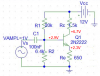
If i start with only the CE amplifier i have this circuit:
**broken link removed**
https://imgur.com/KTW7j

with random values


If i wanna write kirchoff formulas, there are:
Rc + Re = (Vcc - Vce)/Ic

where Vce = (Vcc)/2

and thevenin conditions are:
Rth = R1 // R2
Vth = (Rth/R1)*Vcc
and also:
Vth = Ib Rb + Vbe + Ic Rc with Ic ≈ β Ib

at least:
Av = - Rc/Re

However I have some problems with kirchoff formulas about CC-Ce cascade :confused:

There is my pspice model (gave by school):
https://adf.ly/3Z2SC

(with random values again)

-Vcc + (Vce)2 + I(re2)Re2 =0

where (Vce)2 is for the new resistor.

how must i continue?

i hope someone will help me, thanx.
 
Last edited by a moderator:
Why is your schematic as big as my neighbourhood?
I cropped it and used Ohm's Law and simple artithmatic to calculate the voltages.
 

Attachments

  • transistor.PNG
    transistor.PNG
    62.5 KB · Views: 337
Ah sorry, i thought it was ok.
By the way, my problem is for cascade CE-CC in this picture:
https://imgur.com/4LqyD

Supposed R1,R2,Re and Rc with a value, i must find Re2, i have written these formulas:

- Vcc + Vce + Re2 *I(Re2) = 0

-Vcc + Rc *I(Rc) + Vbe + Re2 I(Re2)=0


are they correct?
 
Your equations looks good.

Ie1*Re + Vce2 = Vbe+ Ie1*Re2

Or

VRe2 = Vcc - (Ic2 + Ib1)*Rc - Vbe1

And don't forget that current that is flow through Rc is equal to:
IRc = Ic2 + Ib1
 
Last edited:
n p n junction
I want to understand how to 'put' the CE + CC configuration in cascade on a breadbord :/ im using a virtual one like that:
https://imgur.com/IS3Z9
I think i must use also the oscilloscope for misurating Vin, Vout and Av = Av1 *Av2
 
Yes I understand this, but what is the physical type of the BJT you are using in the breadboard (2N2222) ??
 
It really helped to me! Thanks a lot!
Another 2 questions:
1. in that figure i dont see the capacitor Cin, its normal or i must put it too on breadbord?
2. In this CC+CE configuration if i wanna find every resistor, i must write kirchoof formulas.
We write in the last topic some of them.

From: - Vcc + Vce + Re2 *I(Re2) = 0
i can find Re2, supposed that Vce = Vcc/2 ----> Re2 = Vcc/(2*I(re2))

From: -Vcc + Rc *I(Rc) + Vbe + Re2 I(Re2)=0
i cand find Rc so: Rc = (Vce/2I(Rc) ) - Vbe/I(Rc)
supposed Vbe = 0,7 Volts.

Is that correct?
[im trying also to write formulas for R1 and R2]
FOR THE CAPACITOR i use in every simulation 100 nF, i think its ok.

what do you think about all this? :)
 
It really helped to me! Thanks a lot!
Another 2 questions:
1. in that figure i dont see the capacitor Cin, its normal or i must put it too on breadbord?
Yes you need to place Cin capacitor in the breadbord
See the attach file.


2. In this CC+CE configuration if i wanna find every resistor, i must write kirchoof formulas.
We write in the last topic some of them.

From: - Vcc + Vce + Re2 *I(Re2) = 0
i can find Re2, supposed that Vce = Vcc/2 ----> Re2 = Vcc/(2*I(re2))

From: -Vcc + Rc *I(Rc) + Vbe + Re2 I(Re2)=0
i cand find Rc so: Rc = (Vce/2I(Rc) ) - Vbe/I(Rc)
supposed Vbe = 0,7 Volts.

Is that correct?
[im trying also to write formulas for R1 and R2]
FOR THE CAPACITOR i use in every simulation 100 nF, i think its ok.

what do you think about all this? :)
Well, you have done a small error in Rc equation

-Vcc + Ic*Rc + Vbe + Ie2*Re2 = 0

Rc = (Vcc - Vbe - Ie2*Re2)/Ic

But we can assume that your power supply voltage is equal 9V and start to choose the component value.

Re2 = 4.5V/4.5mA = 1KΩ

Vc1 = Ve2 + Vbe = 4.5V + 0.65V = 5.15V

Rc = (Vcc - Vc1)/ ( Ic1+Ib2 ) ----> assume Ic1 = 1mA we end up with

Ib2 = Ie2 / (hfe+1)

Hfe from the data sheet
https://www.electro-tech-online.com/custompdfs/2011/11/PN2222A.pdf

I chose Hfe_min = 50 for Ic>1mA

Rc = ( 9V - 5.15V) / (1mA + 90uA) ≈ 3.9KΩ

but if you want more standard resistor value, for example 10K, no problem at all.

Ic1 + Ib2 = (Vcc - Vc1)/Rc = 3.85V/10K = 385µA

I want the voltage gain to be equal 10 times.

Then Re = Rc/5 ≈ 2.2K

Vb = Ie*Re + Vbe = 350uA*2.2K + 0.65V = 1.42V

To find voltage divide resistor values we normal use this equations

R1 = ( Vcc - Vb) / ( 11*Ib)

R2 = Vb/(10*Ib)


But i chose R2 = 10K and

IR2 = 1.42V/10K = 142µA

R1 = ( 9V - 1.42V)/ ( 142uA + 10uA) = 49K ≈ 51K

Cin > 0.16/( F * Rin) = 1uF

F = 20Hz

Rin = R1||R2||(Hfe+1)*Re = 7.7K

I hope this helps
 

Attachments

  • ce+ccx.zip
    3.5 KB · Views: 246
  • 100.PNG
    100.PNG
    39.6 KB · Views: 275
Last edited:
Yes now i can watch your pic.
I noticed that you gave some random value, i think its ok
By the way, Cin that i use more, its 100 nF or 150 nF it depends.

IS Rin = R1||R2||(Hfe+1)*Re = >

1/Rin = 1/R1 + 1/R2 + 1/(hfe+1)*Re ?

For you Vb is Vbe?
 
By the way, Cin that i use more, its 100 nF or 150 nF it depends.
The size of a capacitors is selected that Xc is much smaller then resistance of a cooperating resistor at the lowest frequency of operation Xc=0.1*R.

Xc = 1/(2*PI*F*C)=0.16/(F*C)

C = 0.16/(F*R)

So for Cin = 100nF the signal frequency must be greater then 160Hz


IS Rin = R1||R2||(Hfe+1)*Re = >

1/Rin = 1/R1 + 1/R2 + 1/(hfe+1)*Re ?

For you Vb is Vbe?

Yes this symbol "||" mean connected in parallel resistors.

Vb is the voltage at base of a BJT

Vb = Ie*Re + Vbe
 
Status
Not open for further replies.

Latest threads

New Articles From Microcontroller Tips

Back
Top