Electro Tech is an online community (with over 170,000 members) who enjoy talking about and building electronic circuits, projects and gadgets. To participate you need to register. Registration is free. Click here to register now.
Welcome to our site! Electro Tech is an online community (with over 170,000 members) who enjoy talking about and building electronic circuits, projects and gadgets. To participate you need to register. Registration is free. Click here to register now.
Hello, this component is from Camera olympus OM-D E-M5 Mark III, I tried to find it in shops but they said don't have a anything with numbers "1jU"
Is it Power Inductor? Or something else? Where can I get it or what could use as substitute?
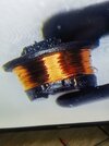
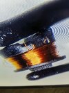
If you can work out how many wires were connected, that will tell you. If there are two ends, it was an inductor. If there were 4, it was a common mode choke.
If it was a choke, that is for noise suppression. If you bypass it by soldering wires across the ends, (near up and down in the photo) it's likely that it will work fine without the choke.
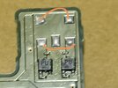
Can you see the wire diameter / number of turns? With 5 wires it's probably a transformer. The two transistors near it are push-pull drivers of a centre-tapped primary. The centre tap is probably the central pad. The opposite two are the secondary, as a guess.
Looking at the PCB it looks more like a transformer than anything else, driven by the two devices immediately below it - it's more likely also a custom component, as most transformers are.
The only place to get one would be Olympus, who probably don't even supply to component level, and only supply to approved service agents anyway.
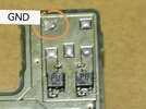
Not really. My guess, based on not really enough information, is that the middle pin is the supply voltage, and is the centre tap. The two transistors operate in turn to ground each end of the centre-tapped winding.
That will be transformed to the secondary. It doesn't make any real difference that one side of the secondary is earthed.
The cover on the component is probably the magnetic screening. That will make modifying a inductor to make it a transformer much more difficult.
There are a couple of OM-D M5 boards on ebay, but I cannot see the part in the photos on those - is it part of the main circuit board, or the screen or viewfinder etc??
Edit - OK, that's not a Mk3 board, I found a video showing disassembly of a Mk3 (which the OP also found).
The only option I can see to get the camera working properly is to replace the entire board, as others have said.
Using a transformer with the wrong number of turns could easily damage other parts, due to excess voltage or current.
[Every time I see that "O M D" model type, I keep getting musical flashbacks, for some reason ]
This site uses cookies to help personalise content, tailor your experience and to keep you logged in if you register.
By continuing to use this site, you are consenting to our use of cookies.