Continue to Site

Welcome to our site!

Electro Tech is an online community (with over 170,000 members) who enjoy talking about and building electronic circuits, projects and gadgets. To participate you need to register. Registration is free. Click here to register now.

  • Welcome to our site! Electro Tech is an online community (with over 170,000 members) who enjoy talking about and building electronic circuits, projects and gadgets. To participate you need to register. Registration is free. Click here to register now.

Can anyone identify these PCB tag terminals on a Jaguar XJ8?

Segillum

New Member
I have a problem with my elderly Jaguar XJ8 which is entirely self-induced but which I'm having trouble solving and any help would be most gratefully received.

A couple of 286-size bulbs in the instrument cluster have expired and it seemed like a good idea to replace them. In typical Jaguar fashion, when they assembled the cluster they started with the bulbs and built the rest round it. So fairly extensive dismantling was required to get at them.

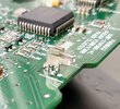
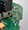
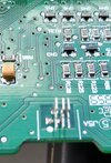
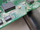
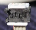
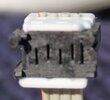
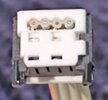
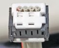
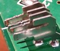
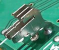
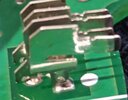
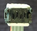
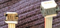
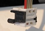
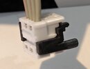
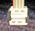
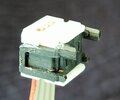
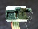
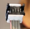
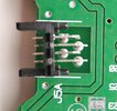
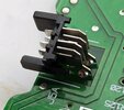
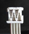
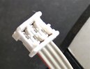
In the process of removing several tiny four-way connectors attached to ribbon cables which connect to the gauges I managed to break two of the blade-type tag terminals on the PCB. No amount of digging through all the usual sources and catalogues has come up with anything that matches them. A couple of photographs are appended and it may not be clear from these that there are actually two different flavours of the terminals. One has the keyway above the blade and the other has it below. However the connectors on the ribbon cables look very similar to me.

I'd be perfectly happy to replace them but for the life of me I can't identify them.

The blades themselves are 0.3mm thick, 7.8mm in length and 1.7mm deep. They sit at about 6.5mm above the PCB.

Can any kind soul identify them and perhaps suggest a source? I’d be extremely grateful for any help.

John
 

Attachments

  • 1683744243796.jpeg
    1683744243796.jpeg
    133.2 KB · Views: 143
  • IMG_20230509_164741262_HDR.jpg
    IMG_20230509_164741262_HDR.jpg
    99.7 KB · Views: 148
  • IMG_20230509_164751756_HDR.jpg
    IMG_20230509_164751756_HDR.jpg
    151.8 KB · Views: 147
  • IMG_20230509_164759469_HDR.jpg
    IMG_20230509_164759469_HDR.jpg
    369.3 KB · Views: 149
Welcome to ETO.

The magic word to use when looking for those connectors is Faston

Look here:

JimB
 
Thanks for that. I spent a good part of this morning looking at the Faston range but couldn't see anything resembling the Jaguar connectors and there's nothing in eBay that looks like them either. The combination of blade and keyway seems very unusual.

In case it's useful, the cluster was made by Visteon, probably not long after they'd been spun out of Ford.
 
I've found another photo of a Jag X100 PCB; it appears the connectors are not individual blades, but part of a PCB connector - there are black plastic shells around them in this other photo?

They presumably have to be bought as complete connectors.

Jag_Cluster_PCB.JPG
 
I've added some pics of the connectors and also made some (hopefully) better ones of the blades. I think the black shells mentioned above are part of the connector but could well be wrong -- as with many Jaguar connectors, these are quite oddball. The dimensions are 8.8 x 7.8 x 6.5mm.
 

Attachments

  • IMG_20230510_214337278_MP.jpg
    IMG_20230510_214337278_MP.jpg
    619.7 KB · Views: 138
  • IMG_20230510_214348390_MP.jpg
    IMG_20230510_214348390_MP.jpg
    564.3 KB · Views: 130
  • IMG_20230510_214442671_MP.jpg
    IMG_20230510_214442671_MP.jpg
    603.2 KB · Views: 134
  • IMG_20230510_214455783_MP.jpg
    IMG_20230510_214455783_MP.jpg
    569.9 KB · Views: 134
  • IMG_20230510_214612872.jpg
    IMG_20230510_214612872.jpg
    1,023.6 KB · Views: 138
  • IMG_20230510_214649960.jpg
    IMG_20230510_214649960.jpg
    896.1 KB · Views: 131
  • IMG_20230510_214730301.jpg
    IMG_20230510_214730301.jpg
    1,017.6 KB · Views: 126
Can you please add photos of the back and sides of the wired part of the connector? All angles, to try and make them easier to recognise?
Preferably with the black part unclipped?
 
>Can you please add photos of the back and sides of the wired part of the connector? All angles, to try and make them easier to recognise? Preferably with the black part unclipped?<

I'm afraid these are probably candidates for the worst photos ever to be offered in a forum but they're the best I can do with the phone camera. Please let me know if you'd like any different angles of the connector or the PCB. I could be wrong but the black part doesn't seem to want to unclip -- it looks like an integral part of the connector.
I
 

Attachments

  • IMG_20230511_092512213.jpg
    IMG_20230511_092512213.jpg
    807.7 KB · Views: 139
  • IMG_20230511_093028646_MP.jpg
    IMG_20230511_093028646_MP.jpg
    1,002.4 KB · Views: 134
  • IMG_20230511_092933030.jpg
    IMG_20230511_092933030.jpg
    396.6 KB · Views: 133
  • IMG_20230511_092908659_MP.jpg
    IMG_20230511_092908659_MP.jpg
    409.1 KB · Views: 127
  • IMG_20230511_092827232.jpg
    IMG_20230511_092827232.jpg
    471.9 KB · Views: 131
  • IMG_20230511_092743425.jpg
    IMG_20230511_092743425.jpg
    439.5 KB · Views: 135
  • IMG_20230511_092710087_MP.jpg
    IMG_20230511_092710087_MP.jpg
    461.7 KB · Views: 133
  • IMG_20230511_092603109.jpg
    IMG_20230511_092603109.jpg
    465.7 KB · Views: 124
Is that a makers logo, as I was hoping for (to the right of the upper groove)?

It's not very clear, being white on white. It it the same on the other connectors, or is it just a scrape on this one?

The black part is the retainer that should have stayed attached to the PCB pins; it probably needs the "ears" at both sides prying outward slightly to release from the cable socket.


Jag_Conn.jpg
 
No, alas, there's no makers' logo in sight anywhere -- they're all anonymous. If I can find my head magnifier I'll have another go at the black clips and report back.
 
Looking at a scrap PCB it seems I got these connectors wrong. The tags on the board are supported or contained by the black shell which I thought was part of the ribbon cable connector. It isn't... my bad.

The PCB and ribbon connector should look like this:
 

Attachments

  • Cluster 1.jpg
    Cluster 1.jpg
    1,023.4 KB · Views: 126
  • Cluster 2.jpg
    Cluster 2.jpg
    878.3 KB · Views: 130
  • Cluster 3.jpg
    Cluster 3.jpg
    703.7 KB · Views: 130
  • Cluster 4.jpg
    Cluster 4.jpg
    449.2 KB · Views: 138

Latest threads

New Articles From Microcontroller Tips

Back
Top