Bob Parihar
Member
i am working on a project which objective is to measure the temperature of surroundings..using AT89s52 micro-controller and ADC0804 for A to D conversion.. the temperature meant to be shown on LCD..
after doing some research i managed to read ADC values coming from the LM35 and displaying it on LCD..
now... finally the tricky thing which i fails to understand...( may be because i won't get any useful material to study)..
so i want to know...
- how to convert the ADC value to corresponding Degree Celsius
-how the step change get affected by varying the Vref/2 and how this affect my code..
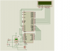
My circuit Diagram and CODE( iam getting the varying ADC value on LCD as i change the temperature) is given as..
#include<reg52.h>
#include"lcd.h"
void delay1(unsigned int);
sbit chipsel =P1^4;
sbit write = P1^5;
sbit intr = P1^7;
sbit readAD = P1^6;
unsigned int val=0,i,j;
void conv();
void read();
void main()
{
init();
while(1)
{
conv();
read();
cmd(0x01);
op(val);
delay(1);
}
}
void conv()
{
chipsel = 0; //Make CS low
write = 0; //Make WR low
write = 1; //Make WR high
chipsel = 1; //Make CS high
while(intr); //Wait for INTR to go low
}
void read()
{
chipsel = 0; //Make CS low
readAD = 0; //Make RD low
val = P3; //Read ADC port
readAD = 1; //Make RD high
chipsel = 1; //Make CS high
}
void delay1(unsigned int y)
{
for(i=0;i<y;i++)
for(j=0;j<1275;j++);
}
the LCD source code is in the attachment with the circuit diagram
after doing some research i managed to read ADC values coming from the LM35 and displaying it on LCD..
now... finally the tricky thing which i fails to understand...( may be because i won't get any useful material to study)..
so i want to know...
- how to convert the ADC value to corresponding Degree Celsius
-how the step change get affected by varying the Vref/2 and how this affect my code..
My circuit Diagram and CODE( iam getting the varying ADC value on LCD as i change the temperature) is given as..
#include<reg52.h>
#include"lcd.h"
void delay1(unsigned int);
sbit chipsel =P1^4;
sbit write = P1^5;
sbit intr = P1^7;
sbit readAD = P1^6;
unsigned int val=0,i,j;
void conv();
void read();
void main()
{
init();
while(1)
{
conv();
read();
cmd(0x01);
op(val);
delay(1);
}
}
void conv()
{
chipsel = 0; //Make CS low
write = 0; //Make WR low
write = 1; //Make WR high
chipsel = 1; //Make CS high
while(intr); //Wait for INTR to go low
}
void read()
{
chipsel = 0; //Make CS low
readAD = 0; //Make RD low
val = P3; //Read ADC port
readAD = 1; //Make RD high
chipsel = 1; //Make CS high
}
void delay1(unsigned int y)
{
for(i=0;i<y;i++)
for(j=0;j<1275;j++);
}
the LCD source code is in the attachment with the circuit diagram