Electro Tech is an online community (with over 170,000 members) who enjoy talking about and building electronic circuits, projects and gadgets. To participate you need to register. Registration is free. Click here to register now.
Welcome to our site! Electro Tech is an online community (with over 170,000 members) who enjoy talking about and building electronic circuits, projects and gadgets. To participate you need to register. Registration is free. Click here to register now.
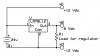
That's is making life a lot more difficult with a 60V source you will have to go into switch mode me thinks unless a very crude fixed voltage regulators are used say one for the + side and one for the - side. The easiest way to do it is use a center tapped transformer and use a circuit like this:
The 7815 is a positive 15v regulator and the 7915 is a negative 15v regulator. It will "create" and regulate the negative voltage from a positive source.
You have an adjustable supply, so start by dialing it down to about 18v. This will keep down the heat dissipated in the regulators.
The 7815 is a positive 15v regulator and the 7915 is a negative 15v regulator. It will "create" and regulate the negative voltage from a positive source.
You have an adjustable supply, so start by dialing it down to about 18v. This will keep down the heat dissipated in the regulators.
That won't work - the 7915 does not create the -15v line - it only regulates it. The 7915 requires a negative input voltage.
For that to work, you would need a +18v line for the 7815 as well as a -18v line for the 7915. To create a negative voltage from a positive one as you suggest, you would need a buck-boost convertor setup.
Thanks everyone.
I was thinking of a voltage divider to get the 3 terminals.
Will that work?
I can connect 2 resistors in series, but any ideas on more improved designs of voltage dividers using readily available, inexpensive ICs etc.
If voltage divider looks ok to everyone, how do i build a more elegant version?
Just 2 resistors in series is very old idea.
It may have loading effects.
Any commonly used transistors, ICs, capacitors etc i might use to implement it?
What I would do is put a 30v regulator, and a 15v regulator, both inputs coming from the supply. The 30v output gets plugged into the +15v, the 15v gets plugged into the common and the 0v gets plugged into the -15v.
You may have to add a heat sink, I'm not sure but I think the regulators might get hot.
If voltage divider looks ok to everyone, how do i build a more elegant version?
Just 2 resistors in series is very old idea.
It may have loading effects.
Any commonly used transistors, ICs, capacitors etc i might use to implement it?
From an efficiency standpoint, this is not much better than just loading the single supply with a resistive voltage divider and then grounding the tap on the divider. The reason is that the "load" resistor has to sink more current than the difference between the current drawn off V+ and V-.
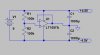
The best way to do this is to get a "power opamp" like an LM675 and wire it as shown on page 2 of **broken link removed**. The "Generating a Split Supply From a Single Supply" circuit exactly splits the input voltage, making it possible to adjust both + and - outputs simultaneously with the voltage control knob on the input supply.
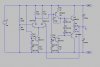
you can create a dual supply from a single voltage supply by using an amplifier as an "active" voltage divider. it's commonly done in onboard guitar electronics using an op amp to divide 9V into +/-4.5V... you will need something a bit more robust than an op amp for the supply you have. as you can see in the pictures, the op amp divider is very simple. for the resistors on the input side, use 1% tolerance resistors. in the second picture, it's exactly the same idea, the power amp circuit is identical except in size to an op amp. again, use 1% tolerance resistors for the input divider. it's a bit more involved of a project, but it can handle the complete 60V output of your power supply, and probably will work ok down to about 15 to 20V. you will know when it stops working, because the ground (actually the half way point of the input voltage) on the output side begins to drift
there are a few circuit notes you will need to know if you want to build the second circuit, such as where to mount the 3-diode string on the heat sink (they act as thermal compensation for the output transistors), etc...
This site uses cookies to help personalise content, tailor your experience and to keep you logged in if you register.
By continuing to use this site, you are consenting to our use of cookies.

")