Continue to Site

Welcome to our site!

Electro Tech is an online community (with over 170,000 members) who enjoy talking about and building electronic circuits, projects and gadgets. To participate you need to register. Registration is free. Click here to register now.

  • Welcome to our site! Electro Tech is an online community (with over 170,000 members) who enjoy talking about and building electronic circuits, projects and gadgets. To participate you need to register. Registration is free. Click here to register now.

Bi-directional LED ?

Status
Not open for further replies.

Mike - K8LH

Well-Known Member
Hey guys, just wondering if any of you have experience using a common LED as an input device (as well as an indicator)? Is it practical or does differing ambient light conditions make it impractical?

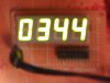
I think it'd be kinda' cool to turn the ALM ON and TMR ON indicators on the right hand side of the Clock below into switches as well as indicators. Currently with this design the Alarm or the Timer display must be selected using the up and down arrow keys in order to switch the Alarm or the Timer on or off with the right arrow key.

Regards...

**broken link removed**
 
JustDIY used to (might still?) have some information on his project blog about using LEDs as touch sensors.
 
Mike, if you drive your LEDs using those left-over analog inputs on your pic (which are also very sensitive schmitt triggers), you should be able to use them bidirectionally.

the problem is, as Jeff demonstrates in his video linked by picasm, the sensors are absolute crap when it comes to ambient light.

Mitshubishi overcomes this problem by modulating the emitter led, but they're using leds for bidirectional communication, not really as a user interface.

use a Qtouch proximity switch and a small loop of wire around the led. you could get one of the bigger qtouch chips and eliminate all your mechanical buttons.
 
justDIY said:
Mike, if you drive your LEDs using those left-over analog inputs on your pic (which are also very sensitive schmitt triggers), you should be able to use them bidirectionally.

the problem is, as Jeff demonstrates in his video linked by picasm, the sensors are absolute crap when it comes to ambient light.

Mitshubishi overcomes this problem by modulating the emitter led, but they're using leds for bidirectional communication, not really as a user interface.

use a Qtouch proximity switch and a small loop of wire around the led. you could get one of the bigger qtouch chips and eliminate all your mechanical buttons.
Thanks for the input. I appreciate the work you've done and the experience you have in this area.

Adding another chip is really beyond the scope of this simple single chip concept/demo so I'll just pass on the idea for now.

Mike
 
At the very least it would require a complete redesign of the LED circuit, in order to use the LED as a sensor it has to be reverse biased. While it's reverse biased it will act as a variable capacitor depending on the amount of light it's P/N junction is exposed to. The micro controller being used might have to be running at a fairly high speed to detect changes in capacitance as small as occur. I'm going to hazzard a guess that that matrix in the google video was probably run off of an FPGA.
 
you don't need to reverse bias the led if all you want is an on/off response.

using the led as a simple photovoltaic on one of the schmitt trigger pic pins should give you a light / no light reading, but generally the reflected light from one led is not enough stimulation for the second led to trigger the desired response.

how about hiding an IR sender and receiver on either side of the indicator led, behind the plastic panel? the plastic will attenuate the ir signal somewhat, but you don't need a 20 ft range.
 
Hi Mike
I must be missing something, but it seems from the schematic that you use same port to drive digits and segments of your display. I believe it can be done by using latches, but I do not see anything like that. Can you please explain how it works?
Thank you Jirka
 
Google "charlieplexing"..... (also sometimes referred to as N(N-1) multiplexing).
 

Attachments

  • Charlieplexed Display Wiring Notes.JPG
    Charlieplexed Display Wiring Notes.JPG
    181 KB · Views: 1,058
  • Stick Display.JPG
    Stick Display.JPG
    59.9 KB · Views: 260
Last edited:
justDIY said:
what's the software look like to drive such a complex matrix?

i've often run into problems where the rule seems to be "the simpler the hardware, the more complex the firmware."
The display wiring is a bit complex compared to traditional multiplexing but the code is probably not as complex as you might imagine. Once you grasp the tri-state requirements and that "float" pin concept the ISR driver code is pretty simple and straight forward. I've seen more complex driver code for standard multiplexed displays in some tutorials.

This example ISR driver for an 8-digit Common Cathode display using 1.0-msec Timer 2 interrupts (12.5% duty cycle, 125-Hz refresh rate) uses about 5-usecs "overhead" every 1000-usec interrupt (0.5% driver overhead);

Code:
;
; The eight LED displays or columns are 'scanned' one at a time
; for a 12.5% LED duty cycle.  Each Port B pin may be sourcing
; current (CC driver) to segments up to 87.5% of the time.
;
ISR_LED bsf     STATUS,RP0      ; bank 1 (RP1 already clear)      |B1
        movlw   b'11111111'     ;                                 |B1
        movwf   TRISB           ; turn off LED display            |B1
        bcf     STATUS,RP0      ; bank 0 (RP1 already clear)      |B0
        xorwf   BITPOS,W        ; invert column/float bit         |B0
        movwf   PORTB           ; new output pattern              |B0
;                                (only 1 output is ever low)
        movf    BUFPTR,W        ;                                 |B0
        movwf   FSR             ; setup indirect address          |B0
        movf    INDF,W          ; get digit segment data          |B0
        andwf   BITPOS,W        ; AND the float/column bit        |B0
        btfss   STATUS,Z        ; turn 'float' segment on?        |B0
        iorlw   b'10000000'     ; yes                             |B0
        iorwf   BITPOS,W        ; pick up the float/column bit    |B0
        iorwf   INDF,W          ; pick up digit segment bits      |B0
        xorlw   b'11111111'     ; invert all bits                 |B0
        bsf     STATUS,RP0      ; bank 1 (RP1 already clear)      |B1
        movwf   TRISB           ; display new digit               |B1
;
        bcf     STATUS,RP0      ; bank 0 (RP1 already clear)      |B0
        incf    BUFPTR,F        ; increment buffer pointer        |B0
        bcf     BUFPTR,3        ; keep in 30..37 LEDBUF range     |B0
        rlf     BITPOS,W        ; rotate the float/column bit     |B0
        rlf     BITPOS,F        ;                                 |B0
 
Last edited:
A single diode as a photo voltaic generator? I just grabbed a square red LED I had off my desk. It generated 50mv's when being shone directly from a bright white LED at point blank range, the highest voltage I could get was 150mv's and that was at an obscure angle which probably focused a little more of the white LED's output onto the diode junction.
 
How come this design uses RB0 to RB7 to turn on the segments and also used them to select different 7-segment display?
 
That particular reduced I/O display multiplexing technique is called Charlieplexing. Here are the 8 pin (no decimal points) and 9 pin version wiring notes;

charlieplexed-display-wiring-notes-jpg.11487
 
Higher impedance? My scopes 1meg.
The OP wanted to keep the setup the same, now we have to use a laser pointer as an input device? Not really practical =) Especially through the display plastic, which has a very limited light entra. Even using the reverse bias method you need an extra I/O pin to act as a charge/discharge switch. The change in a capacitance when reverse biased is only in the pico farrad range from what I've been told so even then it's difficult to measure using pulse discharge. One day I'll play around with it, I'm curious if it would be possible for a simple micro controller to get reliability. I have a feeling a basic switch would be possible but you have ambient light to deal with and that can be a deal breaker. There'd have to be some kind of patterned reception, like an IR's xmitters carrier signal.
 
Last edited:
Yeah, I was hoping to put my fingertip on the LED and use it like a switch (as well as an indicator).

I understand about reverse biasing the LED junction to charge it as a capacitor and then measuring the time it takes to discharge. I just didn't know if you could get consistent readings in different ambient lighting conditions for "finger on" and "finger off" conditions.

Mike
 
charlieplexing!! I thought it is the same as multiplexing.. we need to send the signal to one port only for displaying eight 7-segment displays right? That's smarter than multiplexing.

Can't I use PNP for common anode, can I?

EDIT: Can I still use the look up table if I use charlieplexing? The pattern for displaying the same number for the different 7-segment display seems to be different.
 
Last edited:
Charlieplexing is multiplexing, it just uses a more complex scheme which requires fewer pins than common multiplexing techniques. Look it up in wikipedia. And no, your lookup tables would require at least software conversion into the charlieplexing pattern. The diodes have to be able to withstand being reverse biased at the controllers driving levels though.
 
Status
Not open for further replies.

Latest threads

New Articles From Microcontroller Tips

Back
Top