Peter_wadley
New Member
Ok,
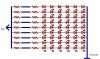
Ive wired the letters up.. included are some pictures of the project (i'm modifying a terminator poster)
The brightness of each letter is very close .. i chose to vary the resistance for each batch of LEDs .. keeping current of each around 22ma...
Now I would like to implement the PIC to control the letters..
I am having trouble wiring this..
I was going to have the PIC to control NPN transistors which would supply 24 volts to the each letter..
The LEDs are wired in series.. so to turn on a letter I must supply positive voltage, which goes through the resistor, then through the batch of LEDs... which then goes to a common GROUND connection which is located on the back of the poster.. (each letter shares a common ground)
The problem is.. how do i wire the transistor to supply 24 volts to the one red wire coming out of each letter?
I understand the load for transistors should be in series .. from the +V to the collector pin..
I am very confused about what to do.
Thanks for any help