Continue to Site

Welcome to our site!

Electro Tech is an online community (with over 170,000 members) who enjoy talking about and building electronic circuits, projects and gadgets. To participate you need to register. Registration is free. Click here to register now.

  • Welcome to our site! Electro Tech is an online community (with over 170,000 members) who enjoy talking about and building electronic circuits, projects and gadgets. To participate you need to register. Registration is free. Click here to register now.

Aromat NAIS relay HX2-4.5V-H12

Status
Not open for further replies.

HarveyH42

Banned
Aromat NAIS relay HX2-4.5V-H12
AHX206 L01
50622H

Searching, I couldn't find a data sheet, but did find some specs.
4.5 VDC, 46 ohms, contacts 1 amp @ 30 VDC, dpdt

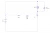
I've been looking through my salvage parts for a 5 volt relay, this was the first one even close that I could find any info on. I need to switch 5 volts around 2 amps for a DC motor, from a ATTiny13 output pin. Figured I'd ask, before hooking it up. Haven't worked with relays much, so just guessing that the MCU can operate the relay directly, and paralleling the contacts should handle the 2 amps max the motor draws. Will I need to provide a diode across the coil to protect the MCU, or will it be fine just to hook it up?
 
4.5 VDC into 46 ohms will net you a current of 98ma which the MCU will not be able to supply. Plus the contacts are only good for 2Amps resistive if you parallel them. You want to switch 2A inductive which is harder on the contacts. You'll need a transistor and different relay.
 
That bites, mostly I'm finding 12 volt relays. Remember having a couple of old modem boards I think had relays, have see if I can find them tomorrow.
 
HarveyH42 said:
That bites, mostly I'm finding 12 volt relays. Remember having a couple of old modem boards I think had relays, have see if I can find them tomorrow.

Sensitive 5 volt relays (25ma or less of coil current) typically aren't made with higher current contacts, one amp probably being the most common rating, although you might find such a critter at some price.

Best prices for high contact current relays are for the 12vdc automobile market. I've seen them on sale often with smaller parts vendors and of course E-bay sellers.

Now a days logic level power Mosfets tend to be a better solution all around then relays if you only need a SPST function.

Lefty
 
I don't much about using power transistors or mosfets, guess its time to learn. Everything in this project runs off 5 volts. The motor only needs to run one direction, and maybe 5 seconds. I'm not expecting it to be triggered very often, maybe 3-5 times over 24 hours. Will dig up some parts, find datasheets and see what I can do.
 
Okay. I found some IRF521 MOSFETs, and if I read the datasheet correctly, 2-4 volts are needed to turn it on. Since I'm running the MCU at 5 volts, I need a small gate resistor.

I did a simple test circuit in LiveWire. Didn't have the IRF521 part, so just went with 'ideal'. Anyway, the Mosfet blew when I released the button. Added a 1N914 (I have hundreds). Both the diode and mosfet blew. Changed to the 1N4004, only the mosfet blew. Raised and lowered the gate resistor, still blows.
So guessing I'm doing something fundimentally wrong. Included schematic I used and the datsheet.
 

Attachments

  • MOSFET.jpg
    MOSFET.jpg
    26.2 KB · Views: 330
  • IRF521.pdf
    81.1 KB · Views: 229
Think I got the burning question answered, but need some practical values. I put a 1 meg resistor from gate to source, and all seems well. But this is just in simulation, and not very accurate or reliable. I only have two IRF521 at the moment, but think I have a similar board some place. Pretty sure I can remove them without damage. Basically, I need to get this right the first time, or start over with a different part. Didn't really get how to calculate the resistors, just guessed...
 
HarveyH42 said:
Think I got the burning question answered, but need some practical values. I put a 1 meg resistor from gate to source, and all seems well. But this is just in simulation, and not very accurate or reliable. I only have two IRF521 at the moment, but think I have a similar board some place. Pretty sure I can remove them without damage. Basically, I need to get this right the first time, or start over with a different part. Didn't really get how to calculate the resistors, just guessed...


I think you need a different device. Looking at the data sheet it doesn't appear to be a logic level device and requires 10v GS to fully turn on. The threshold voltage rating is not the same as full turn on voltage, so you will either have to drive the gate via a small transistor or go with a true logic level Mosfet.

Lefty
 
What happens when the mosfet doesn't fully switch on? I only need 5 volts around 2 amps if the motor stalls. Hoping to keep my power supply for the project at 5 volts...
 
If the MOSFET doesn't fully turn on it will heat up and the motor will not get the full 5V and will turn slowly with little torque. You may be able to find a IRF521 in your bin that'll turn on enough at 4V. I say 4V because you have to allow for the battery running down etc. You'll have to experiment, but I doubt it'll work good enough.
A better solution would be if you can find a logic level MOSFET such as the IRLZ44 etc.
You say that you only have 5V in your system. Running the motor and the MCU from the same supply rail is not the best due to the motor introducing noise onto the MCUs supply rails.
 
Last edited:
Status
Not open for further replies.

Latest threads

New Articles From Microcontroller Tips

Back
Top