Continue to Site

Welcome to our site!

Electro Tech is an online community (with over 170,000 members) who enjoy talking about and building electronic circuits, projects and gadgets. To participate you need to register. Registration is free. Click here to register now.

  • Welcome to our site! Electro Tech is an online community (with over 170,000 members) who enjoy talking about and building electronic circuits, projects and gadgets. To participate you need to register. Registration is free. Click here to register now.

Analyzing an op amp circuit

Status
Not open for further replies.

JasonMcG

Member
See image.
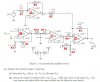
I have tried to decipher what i think is correct.
I've done it in two parts, marked in red and blue and then added the two currents at node P to find Vout. Need to know if i am correct.
Also for the part marked in red. Do you consider the op amp or do you ignore it since it's voltage is zero and use it as a series circuit?
And where do you connect the battery in this circuit?
Must you analyse the circuit at 0.1, 0 and -0.1?
Any and all help is much appreciated.
Thanks.
Circuit_2.jpg

Jason M
 
hi Jason.
The -9V supply is connected to all the Pin #4's of the OPA's and +9V to all the pin #7's

You are asked to analyse with a 0.1Vdc signal into Vin [ some countries use a comma in place of a full stop for decimals] and a 0.1Vpp at 1KHz.

E.

EDIT:
We could work thru it OPA by OPA if you wish.??
 

Attachments

  • Circuit_2.jpg
    Circuit_2.jpg
    67.5 KB · Views: 284
Last edited:
If we could do that it would be a great help. This is my first time doing this and I'm not really sure what to do.
 
If we could do that it would be a great help. This is my first time doing this and I'm not really sure what to do.

hi J,
Use the marked up drawing for reference.

Amp 'A' , is an inverting amplifier with a gain [ or attenuation] of -Gain = R2/R1

Amp 'B' is a non inverting amplifier, so +Gain= 1+ [R4/R3]

Amp 'C' is non inverting 'buffer' with +Gain of 1

Amp 'D' is a 'summing' amplifier.

The -Gain1 = R7/R5,,,,,,,,, -Gain2 = R7/R6

The non inverting input voltage 2V is divided by R8 and R9, so +vin =1V

So for Amp 'D' the over all gain is ???
[remember that R5 and R6 are in parallel as far as the gains for Amp 'D' are concerned]

For Amp 'C' , R10 and R11, with the 1uF form a low pass filter, ignore this for the DC analysis.


So you work out the gains of Amps A , B and C first, then post the results, then we will cover Amp 'D'


BTW the Vout you have worked out is wrong.
 
hi J,
For Amp 'D'

Consider the output of Amp 'D', due to each input.

Amp 'A' input -0.9V input , as 'D' an inverting amplifier with a gain of 100k/100k =1
the 'D' output would be +0.9V

Amp 'C' input of +1.1V, again 'D' is inverting with a gain of 100k/10k = 10
the 'D; output would be -11.0V

On Amp 'D' the non inverting gain would be 1+[100K/9091] [ rem 100K || 10K] =11+1
So 'D' output would be 12*1V = 12V.

If you now take the algebraic sum of those outputs you should get +1.9V as Vout.

OK.???
 
Last edited:
I understand everything except the last part where it says:
"On Amp 'D' the non inverting gain would be 1+[100K/9091] [ rem 100K || 10K] =11+1
So 'D' output would be 12*1V = 12V."
What is 9091?
 
I understand everything except the last part where it says:
"On Amp 'D' the non inverting gain would be 1+[100K/9091] [ rem 100K || 10K] =11+1
So 'D' output would be 12*1V = 12V."
What is 9091?

hi J,
The R5 and R6 are in parallel when you calculate the non inverting gain.

So 100K and 10K in parallel is 9091 Ohms... this means the gain for the non inverting is 100K/9091 = 11 + 1 =12

Do you follow ok.?
 
Oh yes i see. Converted everything to ohms. Makes sense now. Thanks a million for all your help. You taught me a lot.
For the second part what exactly are you supposed to do. If you could give me pointers it would be greatly appreciated.
You supposed to use alternating current i think so must you find the outputs at -0.1, 0 and 0.1?

The 2nd question says use a 1000Hz sine wave with an amplitude of [0.1v] 100mVolt peak to peak.
A 100mV peak to peak means the sinewave goes upto +50mV from 0V then back down to -50mV

You have to calculate the effect of the 1uF capacitor and the 100 Ohm resistor has on the signal amplitude between Amp 'B' and the input of Amp 'C' [ it will be reduced]

The Impedance of the 1uF at 1KHz is Z= 1/[ 2*∏ * 1Khz * .000001]

As a check on the Vout from Amp 'D' make Vin = 0v, lets know what you calculate for Vout.???
 
Hi,

I have not been able to figure out what exactly to do. I tried searching impedance but not exactly sure what it entails. How do I go about using this impedance value?
 
Hi,

I have not been able to figure out what exactly to do. I tried searching impedance but not exactly sure what it entails. How do I go about using this impedance value?

hi J,
I have posted the formula: The Impedance of the 1uF at 1KHz is Z= 1/[ 2*∏ * 1Khz * .000001]

I would suggest you calculate the Vout for the following three values of Vin.
+50mV DC, 0V and -50mV DC, this will help when you come to plotting the waveform at the output.

Recall that Vout is +1.9V with a 0.1V dc input.

Hint: when you calculate Vout for 0Vin the Vout will be saturated at the supply voltage.

Work out the 1uF impedance and post the value.

E.

OT: which part of RSA are you located.?
 
I have gone through part one again and calculated Vout to be 23.9V. For amp B the gain is 11 multiplied by the voltage of -0.1V gives you -1.1V. Therefore in the end you will have 0.9+11+12= 23.9V. Am i correct in saying this?
 
I have gone through part one again and calculated Vout to be 23.9V. For amp B the gain is 11 multiplied by the voltage of -0.1V gives you -1.1V. Therefore in the end you will have 0.9+11+12= 23.9V. Am i correct in saying this?

hi Jason
Sorry, but your answer for Part 1 is very wrong.

Consider Amp 'D'

Look at this image, I have simplified to show just Amp 'D'

The -0.9v input is amplified by times 1 by D and its also inverted so it comes out of D as +0.9V

The -1.1v input is amplified by times 10 by D and its also inverted so it comes out of D as -11V

The +1v input is amplified by times 12 by D and its NOT inverted so it comes out of D as +12V

If you add those 3 outputs together, algebraically you should get +1.9V

Check you calculations and post how you have worked it out.

E.
 

Attachments

  • AAesp05.gif
    AAesp05.gif
    7.5 KB · Views: 281
hi J,
I think I may have misread the -0.1Vin as 0.1Vin...........give me a while to recheck..

E.

EDIT:
I did misread that input, sorry about that.:eek:

The output would want to rise to 23.9V, but as the OPA Supply is only +9V, it would not be able to rise to +23.9V.

The 741 OPA has a saturation voltage of Vsupply -1.5V ie: [9v-1.5=7.5V] with a 9V supply, so the Vout would be around +7.5V

So the figures I posted earlier should read:

The -0.9v input is amplified by times 1 by D and its also inverted so it comes out of D as +0.9V

The -1.1v input is amplified by times 10 by D and its also inverted so it comes out of D as +11V

The +1v input is amplified by times 12 by D and its NOT inverted so it comes out of D as +12V

If you add those 3 outputs together, algebraically you should get +23.9V [ But the in practice it would only reach around +7.5v]
 
Last edited:
The impedance value i get is 6.283*10^-3 ohms.
I stay in Johannesburg on the East Rand.

hi J,
You have now got to invert that answer: its 1 / 6.283*10^-3 Ohms

The formula is: Zc = 1 / [2 *pi * F * C]

E.

OT: I visit PE for 2 months each year.
 
I now get 159.15 ohm.
You have family in PE?
Are you an electrical engineer? if you don't mind me asking.

hi.
That value of 159R is close enough.

So you have now R10 [100R] in series with that Xc impedance of 159R, which will divide the signal from pin #6 to a lower value.

From pin #6 of Amp 'B' you have the Vin 0.1V peak to peak amplified by 11 times, so on pin 6 is a sine wave of 1.1V pk to pk
this means a peak positive half sine wave of +0.55V swinging thru 0V down to -0.55V.

Work out the sinewave amplitude at the junction of R10 and the 1uF cap, lets know what you get.

E.
Left click your mouse on my name above my Avatar image to see my profile.
Yes I have family in PE
 
hi J,
From which document or book did that circuit question come .?

Its about the worst example I have seen for student to learn about OPA's.

You obviously need to learn about OPA saturation, but there are better ways to be taught, IMO.

E.
 
It's not from a textbook. It's from a book compiled by one of our lecturers. He expects us to learn everything ourselves so I'm trying.
To find the amplitude at the junction, do you first need to find out the current?

Jason M
 
Status
Not open for further replies.

Latest threads

Back
Top