Continue to Site

Welcome to our site!

Electro Tech is an online community (with over 170,000 members) who enjoy talking about and building electronic circuits, projects and gadgets. To participate you need to register. Registration is free. Click here to register now.

  • Welcome to our site! Electro Tech is an online community (with over 170,000 members) who enjoy talking about and building electronic circuits, projects and gadgets. To participate you need to register. Registration is free. Click here to register now.

Amplify ALESIS Drum Kit Cymbal using TL082

Menticol

Active Member
Hello guys!

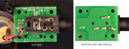
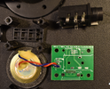
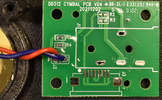
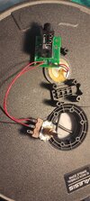
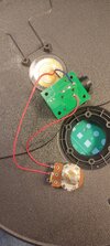
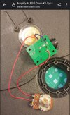
I'm having some issues with my drum kit. The drum kit works as follows: The drum kit has a piezoelectric sensor attached to the pad (see attached photos). When the pad is hit the drum's "brain" module receives a pulse from the piezo sensor, presumably after passing through a voltage divider, and plays a sound. The volume of the played sound is somewhat proportional to the energy of the impact against the pad. The played sound is a pre-recorded file and has no resemblance of the received impact signal.

The problem is that the cymbals of my electronic drum kit are much quieter than the snare drum, and do require an excessive force to play at a reasonable volume, making the playing experience very strange.

Since the "brain" of my drum kit doesn't provide a way to adjust the sensitivity of each pad, I was thinking of putting a little OP amp between the piezoelectric sensor and the brain, with a potentiometer to adjust the gain.

I bought a TL082 Opamp and tried to follow another post on this forum where the OP also was trying to amplify a piezo signal. But my electronics knowledge is very basic and I'm not sure how to calculate the adequate resistor values to reach the specific gain/voltage, or how to run the TL082 on a single rail supply and not have the risk of frying the drumkit brain (the brain uses a singe rail 12V supply).

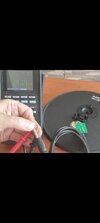
Attached is the output of the cymbal connected to an oscilloscope, showing the quieter signal and how much gain would be needed.

Any tips will be very appreciated


oscilloscope.png
cymbal.png
opamp.jpg
 
Last edited:
The principle of using a single supply to emulate dual rail supplies is to have a resistor divider that gives half the supply voltage; eg. two 1K resistors in series. Add a capacitor from the mid point to ground, eg. 10uF or 100uF.

Then use the mid point as "ground" as far as the biasing of the opamp is concerned, so the + input would connect to that in your "typical connection" diagram.

The piezo discs are very high impedance, so the input resistor should be at least 47K.
Using an eg. 500K or 1M pot as the feedback resistor (output back to input) would give a gain from zero out to 10x or 20x gain out.

Add a 0.1uF between the opamp out and the Alesis input.

The Piezo triggers can easily give tens of volts though, so I don't know how linear it will be, with a 12V limit?


I'm surprised the Alesis unit has no adjustments? Mine (DM-10) has vast range of input tuning settings?

You may be better off trying a new piezo disc in the cymbal itself, and checking whatever touches the disc has not degraded or worn.

I have a virtually unused one I could check with a scope to see what the output voltage is, if I can remember where I stored it?
(I replaced it with the Pro X hihat on mine).

DrumKit.jpg
 
Awesome response Rjenkinsgb, thank you very much! This is the "Turbo" Alesis kit, very basic, is the cheapest one on the range but the only one I could afford.

The kit is brand new and even Alesis has acknowledged the quality issue with the sound, but I awaited too long and I'm unable to replace it. They suggested to use it connected to a computer MIDI to replace the defective sound, but I love the electronics challenge.

Someone on the internet changed the value of the resistors in the voltage divider on the cymbal PCB, but I don't like this approach due my poor SMD experience and not knowing the correct values.

From the oscilloscope I conclude that the cymbal signal never goes up to 3 or 4 volts due the voltage divider pcb. Does your resistor value suggestion limit the amplifier output to that peak value, regardless if the op amp is fed with 12v at Vcc?

Again, thank you very much for your time
 
Sure! Let me know if you can follow the traces. I can desolder the jack if you prefer. The ugly yellow wires are my oscilloscope leads.

PS: On the right side I tried to add an "x-ray" version of the board's backside, please disregard the "inverted" caption, I just realized that word makes no sense on this context
 

Attachments

  • side1.png
    side1.png
    3 MB · Views: 120
Last edited:
I home I'm seeing things there! That divider ratio looks insane.

Can you measure the resistance across the cymbal, using the cable that plugs in to the main box to ensure it's the correct connections?
 
Sure thing! The end that connects to the main box ends into a wire loom with a multi pin connector shared with the other pads, it was hard to measure. So instead I connected a mic cable to the cymbal instead. Would that be valid? The result was 141.4 Kilo ohm
 

Attachments

  • Screenshot_2023-09-21-15-33-42-246_com.miui.gallery.jpg
    Screenshot_2023-09-21-15-33-42-246_com.miui.gallery.jpg
    409.2 KB · Views: 100
  • Screenshot_2023-09-21-15-32-46-416_com.miui.gallery.jpg
    Screenshot_2023-09-21-15-32-46-416_com.miui.gallery.jpg
    507.9 KB · Views: 100
There is something still very strange with that..
I suspect there is an open connection somewhere.

Using the mic lead, measure the resistance of each of the four combinations, from tip & sleeve to each of the piezo disc connecting wires, on the back of the PCB?

Also, be careful not to bridge the meter connections with your fingers, as that can throw off high readings such as these - the 141K could just have been via skin contact?

ps. It may also be worth treating all the jack plugs in the system with contact cleaner/lubricant, 3 in 1 or other thin oil. Wipe it off so there inly a fine film left, then plug and unplug each in its respective socket a few times.

Typical cheap jack plugs with a hard playing can tarnish to the point they lose contact, or it becomes high resistance.
 
Hi rjenkinsgb! No time no see

I'm sorry for the delay. As the saying states, "The lazy person ends up having to work twice". De-soldering the jack was the obvious thing to do on my part, instead of wasting your time

I hope you find the following pictures much more decent

Took the measurement again, and the resistance value between the two output leads that go to the drum module is 150 k ohm. The resistance between the piezo leads reads 197.1 k ohm (without desoldering any existing resistors from the board). Let me know if you still need other resistance values.

PS: The Alesis guys acknowledged the too-quiet sound issue here but facing the pain of reaching and wrestling with customer service, paying the shipping, and sending the kit... what a nightmare. A DIY solution would be preferable!
 

Attachments

  • general1.png
    general1.png
    2.4 MB · Views: 101
  • board1.png
    board1.png
    3.5 MB · Views: 131
Last edited:
Try adding a link from the piezo red wire terminal to the output on the jack?
That should bypass the 47K series resistor and increase the sensitivity somewhat.

Some people have added extra piezos on some other Alesis cymbals, wired in series to give a higher output!
 
But could that increase the gain excessively? Do you think the OP amp approach would be worth it, to have better control?
From the PCB pictures it appears there's a huge attenuator on the output of the piezo, a 47K resistor for the top value, and an 18 ohm for the bottom value.

I'd suggest removing the 18 ohm resistor, and seeing what the gain is like then (it should be massively higher) - then try adding different values in place of the 18 ohm, to get the gain you desire.

Bypassing the 47K, would just leave the 18 ohm directly across the piezo - assuming it's wired how it looks in the pictures - and that would severely dampen the piezo, and also still reduce the gain massively.

There seems no point whatsoever adding an opamp, when it looks like they just fitted the wrong value resistor?.

Assuming it was a mistake in the resistor value, it 'might' be supposed to be an 18 'something', so I think I might try an 1.8K resistor for a start (182) - or temporarily wire a 10K pot in it's place, and adjust that for the gain you desire, then measure what it's set to, and install a fixed resistor of that value.
 
From the PCB pictures it appears there's a huge attenuator on the output of the piezo, a 47K resistor for the top value, and an 18 ohm for the bottom value.
That's exactly why I wanted the resistance values measured, as it did not make sense. 18 Ohms would give near enough zero out, while drum pads etc. typically give several volts, or even tens of volts, on a hard strike.

The fact that the resistance across the piezo is ~200K means the 18? resistor is actually around 150K or more (180K?)

Or possibly 18D, 18K, using the letter code multiplier format? But that still does not match the piezo terminal resistance.


Edit - if that is actually 18K, it implies the 47K is faulty or damaged?

But could that increase the gain excessively? Do you think the OP amp approach would be worth it, to have better control?
Try it - if it's then too sensitive, remove the 47K resistor and wire eg. a 47K / 50K across the piezo to output, so you can optimise the sensitivity to anywhere between those extremes.
 
Hello guys! I have great news. At first tried Nigel advice of connecting a 10K ohm potentiometer in place of the mysterious 18 something. No difference. So I went into extreme mode and replaced the 47k ohm resistor with a 50k ohm potentiometer. The sound volume is perfect now. I was thinking to return the 18 something result back to it's place, but I misplaced it.

Sorry for the horrendous soldering!

Screenshot_2023-09-27-12-43-10-006_com.miui.gallery.jpg
 

Attachments

  • Screenshot_2023-09-27-12-43-21-540_com.miui.gallery.jpg
    Screenshot_2023-09-27-12-43-21-540_com.miui.gallery.jpg
    2.3 MB · Views: 126
This could be the final version of the fix unless you have any additional advice (i.e. re-adding the 180 mystery resistor). Looks good for you guys?
 

Attachments

  • Screenshot_2023-09-27-13-09-22-789_com.miui.gallery.jpg
    Screenshot_2023-09-27-13-09-22-789_com.miui.gallery.jpg
    2.1 MB · Views: 118
  • Screenshot_2023-09-27-13-29-39-557_com.miui.gallery.jpg
    Screenshot_2023-09-27-13-29-39-557_com.miui.gallery.jpg
    1.2 MB · Views: 106
Last edited:
Great stuff!

If you measure the value of the pot once you have the adjustment dialled in, you could put a fixed resistor in place of that.

Or just use a small preset resistor that will fit behind the jack socket. Just be sure whatever it ends up with is vibration proof!
 

Latest threads

New Articles From Microcontroller Tips

Back
Top