Continue to Site

Welcome to our site!

Electro Tech is an online community (with over 170,000 members) who enjoy talking about and building electronic circuits, projects and gadgets. To participate you need to register. Registration is free. Click here to register now.

  • Welcome to our site! Electro Tech is an online community (with over 170,000 members) who enjoy talking about and building electronic circuits, projects and gadgets. To participate you need to register. Registration is free. Click here to register now.

90W offline Flyback with all PTH components

Status
Not open for further replies.

Flyback

Well-Known Member
Hi,
Doing a 90W QR flyback off 400Vdc, 60V, 1.5A out. 39kHz at max load.

Its all in PTH. Not even SMD for the controller.
Do you think this will be ok noise-wise? We are going to damp the FET turn on and off to reduce noise. Also, there will be a current sense filter….but all PTH.

Ive never done this power level in all PTH before….do you know if its workable?
 
Thanks, but i ususally find that the current sense filter needs to be layed out really tight, and the lead inductance of thru hole could be a killer for it?
 
Maybe time I contribute again lol. I've become very clever and versed in the "African way" of doing stuff. lol.
 
People were manufacturing things long before SM
Thanks, yes, thats what worries me...in the days before SMPS existed or were common.....also, the old SMPS's switched at low frequency , and the rise times were far slower than today, so they were much more damped, and thus the noise wasnt a problem.........i think SMD has been with us at least as long as SMPS have been in high volume circulation(?).
 
My first switcher was in about 1980.
I know engineers that built "flyback power supplies" in the early 1930s.
 
I really wasn´t there in the 1980s designing switchers, but I believe the demands that the IEC standards required back then regarding radiated and conducted emissions were quite different from what we have today.
Actually did the IEC or common standards exist back then, or did each country have its own regulations?
 
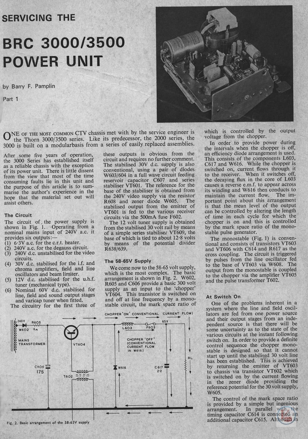
The first domestic use of a switch-mode PSU was in the Thorn 3000 colour TV about 1969/1970.
Thanks, i'd love to know what f(sw) they used.....and whether it was BJT.......also what type of ferrite, if actually ferrite.
I wonder what was the reverse recovery time of the diodes used?
 
The first domestic use of a switch-mode PSU was in the Thorn 3000 colour TV about 1969/1970.
I worked with an engineer that built a "TV" for the world's fair. Before TV was a thing. The CRT was in a long-necked beaker. No sound. It only demonstrated you could project a moving picture onto a screen with electrons. The high voltage was made with a "flyback" pulse. He told me they did not understand why they were getting a pulse, but it was a very efficient way to make high voltage.

I met an engineer whose TV set mostly ran off of the flyback transformer. The vertical, audio and video lived off the FB transformer. The FB and the maim power transformer were the same thing. He varied the Horizontal switch timing to get just enough to regulate the power line to a constant output of the transformer. I never saw a schematic so can't talk about how it works. I think that series of TVs were "hot chassis" where the power line goes directly to the horizontal section without isolation. The rest of the TV has isolation via the transformer.

Because I built monitors/TV, when I first saw a resonant/ qusi-resonant switching power supply I knew exactly how they work. To me the very high frequency switching supplies are very much a horizontal section of a TV. My larger color displays had resonant supplies.
 
Thanks, i'd love to know what f(sw) they used.....and whether it was BJT.......also what type of ferrite, if actually ferrite.
I wonder what was the reverse recovery time of the diodes used?
BJT, no FET's back then - and for their better reliability BJT continued to be the transistor of choice, a few models over the decades 'experimented' with FET's, but they suffered from poorer reliability. The transistor used was labelled R2010, an in-house number, and the inductor was some kind of ferrite.

 
I worked with an engineer that built a "TV" for the world's fair. Before TV was a thing. The CRT was in a long-necked beaker. No sound. It only demonstrated you could project a moving picture onto a screen with electrons. The high voltage was made with a "flyback" pulse. He told me they did not understand why they were getting a pulse, but it was a very efficient way to make high voltage.

I met an engineer whose TV set mostly ran off of the flyback transformer. The vertical, audio and video lived off the FB transformer. The FB and the maim power transformer were the same thing. He varied the Horizontal switch timing to get just enough to regulate the power line to a constant output of the transformer. I never saw a schematic so can't talk about how it works. I think that series of TVs were "hot chassis" where the power line goes directly to the horizontal section without isolation. The rest of the TV has isolation via the transformer.

Because I built monitors/TV, when I first saw a resonant/ qusi-resonant switching power supply I knew exactly how they work. To me the very high frequency switching supplies are very much a horizontal section of a TV. My larger color displays had resonant supplies.
Thorn also later introduced the 9000 series, using what they called a 'Syclops' circuit, with just one transistor and transformer providing both SMPSU and line output - it would also work from 90V to about 280V mains. They were generally fairly hated in the service trade, but I had no issues with them, and they were the first PIL tube sets as well. They did have an incredible number of rectifiers and diodes in their circuit :D
 
They were generally fairly hated in the service trade
It is possible to make something that just about can't be repaired. It is a good idea for an engineer to go to the repair area and see what they think of the new product. I learned, by going to production and asking how I could make their life better.

I spent too much time last week chasing a problem. Next revision of the PCB will have a way to turn off much of the board and them turn on one piece at a time.
 
It is possible to make something that just about can't be repaired. It is a good idea for an engineer to go to the repair area and see what they think of the new product. I learned, by going to production and asking how I could make their life better.
They were fairly easily repairable, and reliable anyway, it was just that it looked complicated, because two major parts of the set were integrated in a single module. As in most trades, engineers tend not to like anything new - because I was mainly a bench engineer, I got all the sets that were brought back for repair, so I was well experienced with them.

I even repaired various ones in customers houses, locating and replacing faulty rectifiers etc.

In one 'famous' case I had a massive row with a vicar :D

We had a service call from the vicarage a couple of villages away, Thursday morning (we only worked half day Thursday), and the vicar said his son would be in. So I went along, knocked on the door, couldn't get any reply - but did notice a moped parked outside?.

Anyway, about 12:50 the vicar rang up (we closed at 13:00) playing absolute hell that nobody had been, so he was passed through to me - and I pointed out I'd been, but couldn't get any reply. Anyway, the vicar was going crazy at me, demanding someone went out immediately - so I pointed out that there was a moped parked outside, to which he replied his son didn't have a moped. So I suggested it was probably his sons girlfriend's moped, and they were two busy sh*gging to bother answering the door :D

Next day I went along again, while the vicar was there, and repaired the set by replacing one of the afore mentioned rectifiers - the vicar was a nice as pie, gave me coffee, gave me biscuits - and I managed to avoid asking if his son had enjoyed the previous morning? :D
 
Status
Not open for further replies.

Latest threads

New Articles From Microcontroller Tips

Back
Top