Continue to Site

Welcome to our site!

Electro Tech is an online community (with over 170,000 members) who enjoy talking about and building electronic circuits, projects and gadgets. To participate you need to register. Registration is free. Click here to register now.

  • Welcome to our site! Electro Tech is an online community (with over 170,000 members) who enjoy talking about and building electronic circuits, projects and gadgets. To participate you need to register. Registration is free. Click here to register now.

7 segment

Saeedk9574

New Member
Hi everyone
I am using a common anode 4 digit 7 segment to show the time, but the problem is whenever I increase voltage above 3.8v All LEDs of the 7 segments gets lighted up and the correct number can not be seen
I have connected the common pins (A-G) of 7 segments to the PNP transistor, and the common pins connected to 300-ohm resistor.
 
Code works well, the problem occurs above 3.8v.
That doesn't mean the code isn't the problem - for example if the I/O pins are set as open-collector that could well cause problems as the voltage increases.

However, as this is the ARM forum, why does your diagram show a PIC18F? - I would also assume an ARM is 3.3V only, and you can't feed the PNP transistors from much higher than that or they will always be ON, just like you're experiencing.

THis is why you need to post exactly what you've built, and not a schematic for something totally different.
 
I would also assume an ARM is 3.3V only, and you can't feed the PNP transistors from much higher than that or they will always be ON, just like you're experiencing.

You hit the nail on the head, Nigel - his breadboard setup shows an STM32 "Blue pill" style module, which is 3.3V internally.
 
When you hit 3.8V the LDO 3.3V regulator going into regulation so its
GPIO never go above 3.3 hence PNP never gets shut off ? Per Nigels
comments.

Keep in mind todays LEDs are high bright process (typically) so even
uA will start the LEDs glowing ? Basically current creates photons and
logarithmic eye response is sensitive enough.... And then you have C
coupling of mux operation noise into PNP bases adding to problem, so layout
important consideration. Prototype grounding and supply stiffness also
add to issue.


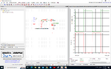
SIM, using cursor measurement, shows > 10 uA Iled with a 500 mV base drive, eg.
when its supposed to be "off" -

1699362414972.png


Regards, Dana.
 

Attachments

  • 1699362003591.png
    1699362003591.png
    174.6 KB · Views: 78
Last edited:
Since you
When you hit 3.8V the LDO 3.3V regulator going into regulation its
GPIO never go above 3.3 hence PNP never gets shut off ?


Regards, Dana.
Right.

He can try setting his anode control pins to INPUTS to turn them off. Then swith the desired digit to output low to turn the PNP on completely. This assumes there is no significant leakage into the input pin from the PNP emitter.
 
Since you
Right.

He can try setting his anode control pins to INPUTS to turn them off. Then swith the desired digit to output low to turn the PNP on completely. This assumes there is no significant leakage into the input pin from the PNP emitter.
The only tricky thing is the parasitic diode clamp on inputs and outputs will provide a
path for Ibase when emitters are taken greater that a diode drop above Vdd rail of
processor.

Regards, Dana.
 
Since you
Right.

He can try setting his anode control pins to INPUTS to turn them off. Then swith the desired digit to output low to turn the PNP on completely. This assumes there is no significant leakage into the input pin from the PNP emitter.
No use, the protection diodes will clamp the pin to the 3.3V rail.

He needs to add NPN drivers feeding the PNP transistors, as per the fifth picture on my 'hardware extras' page:

 
the problem is whenever I increase voltage above 3.8v All LEDs of the 7 segments gets lighted up
There is no reason to increase the supply above 3.3V so why is it a problem?

Are you trying to source LED power elsewhere? Is there some other hidden problem unspecified?
 
Some possible work-arounds:

1: Use the combination of base-emitter resistor and MCU to base resistor as a divider, so the difference between the MCU 3.3V and the LED positive supply does not turn the transistors on, but near 0V in to the resistor does.
eg. for 5V supply, the input resistor 3 to 4 times higher than the base-emitter resistor.

2: Add eg. three signal diodes in series with the base resistor, using equal base input and b-e values.
A low voltage zener such as 2.1V could be used in place of multiple diodes.

3: Add an external IC - a 74HCT138 or 139 decoder, operating from the 5V LED supply & use that to drive the transistor bases.

The required transistor would then be selected by a binary code rather than individual pins.
(Very useful if you want to drive eight digits, only three pins needed on the MCU, or four with enable used).

Note it must be the HCT version for such voltage translation - those have TTL level compatible inputs, so 2V "high" threshold, ideal for 3.3V logic. Normal HC series have input thresholds proportional to the supply voltage.
 
Some possible work-arounds:

1: Use the combination of base-emitter resistor and MCU to base resistor as a divider, so the difference between the MCU 3.3V and the LED positive supply does not turn the transistors on, but near 0V in to the resistor does.
eg. for 5V supply, the input resistor 3 to 4 times higher than the base-emitter resistor.

2: Add eg. three signal diodes in series with the base resistor, using equal base input and b-e values.
A low voltage zener such as 2.1V could be used in place of multiple diodes.

Both solutions are quite 'nasty' and less reliable than using simple NPN drivers as I suggested above in post #27 - you could of course also use N-FET's instead of NPN to drive the PNP transistors.

There are also suitable highside driver chips available, but less likely to be 'in your spares box' (they aren't in mine!) than simple NPN transistors :D
 
Both methods effectively limit the current flowing through the LEDs, preventing them from turning on fully when the voltage rises above a preset level. However, I think using NPN transistors to drive PNP transistors or using high-side driver ICs is generally considered a more reliable and efficient solution. The full review on the site
 
Last edited:
You haven't got a pic18lf46k22 by error by any chance?
Your picture shows more circuitry than the schematic.. I see an arduino with an LCD screen??
I use that board for testing different projects which it is included a stm32 f103. I used LCD to get sure that external RTC works well. There is no error in code.
 
That doesn't mean the code isn't the problem - for example if the I/O pins are set as open-collector that could well cause problems as the voltage increases.

However, as this is the ARM forum, why does your diagram show a PIC18F? - I would also assume an ARM is 3.3V only, and you can't feed the PNP transistors from much higher than that or they will always be ON, just like you're experiencing.

THis is why you need to post exactly what you've built, and not a schematic for something totally different.
My microcontroller is stm32f103. I found this diagram on internet and make my circuit bade on this diagram
 
My microcontroller is stm32f103. I found this diagram on internet and make my circuit bade on this diagram
Sorry, but you did so poorly - you can't just mix 3.3V and 5V - adding the required NPN drivers as per post #27 will solve the problem correctly. You would also need to invert the polarity of the I/O pins to compensate for the inversion of the transistor, but that's a trivial change.
 
In future you would get better advice if you provide ACCURATE information rather than telling us that you were using a different micro to the one that you were actually using.

Les.
 

Latest threads

New Articles From Microcontroller Tips

Back
Top