Continue to Site

Welcome to our site!

Electro Tech is an online community (with over 170,000 members) who enjoy talking about and building electronic circuits, projects and gadgets. To participate you need to register. Registration is free. Click here to register now.

  • Welcome to our site! Electro Tech is an online community (with over 170,000 members) who enjoy talking about and building electronic circuits, projects and gadgets. To participate you need to register. Registration is free. Click here to register now.

555 Timers

Status
Not open for further replies.

dknguyen

Well-Known Member
Most Helpful Member
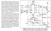
Interesting little things...never had to use one before but I came by a bootstrap capacitor high-side FET driver that required one. It is used as a 15V floating charge pump to refresh the boostrap capacitor in order to allow for continuous duty cycles.

It appears that dv/dt can transients mess around with the transformer interwinding capacitance in isolated floating supplies and I couldn't seem to find a 15V floating charge pump IC so I had to go over how a 555 works.

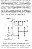
I never knew their comparators were set to 1/3Vcc and 2/3Vcc. Makes the RC time constant directly correlate with the pulses. I always assumed it triggered at Vcc and 0V which I thought was pretty inconvenient since RC time constant only represents 2/3 charge or 1/3 discharge.

Well that's one thing where a PIC can't replace a 555 timer - high voltage applications.
 
Last edited:
Yes, voltage doubling is one of my favourite uses for 555s.

Could you please post a schematic or is it top secret?:D
 
As top secret as International Rectifier is.

I dunno, I just think charge pumps are so cool because it's one of those things where you're like

"It's pretty obvious. Charge up a capacitor to +V and then move it to somewhere else in the circuit and connect it's negative terminal to +V to get +2V."

Except that it was so cumbersome in my mind (I don't have access to all this custom silicon) to pull this off that it never occured to me that someone might pull this off in a wafer foundry. THat's just me. When I first started out in circuits the idea occured to me very early on, except I was like, "Naaaaahhh...too much switching going on. No one would ever do something like that." Of course, it had never occured to me at the time to use an RC-based timers rather than a crystal.
 

Attachments

  • IRF.jpg
    IRF.jpg
    127 KB · Views: 1,206
Last edited:
dknguyen said:
When I first started out in circuits the idea occured to me very early on, except I was like, "Naaaaahhh...too much switching going on. No one would ever do something like that." Of course, it had never occured to me at the time to use an RC-based timers rather than a crystal.
I tried to design and build a charge pump when I was about 12, from an astable multivibrator and some transistors, it would've worked too if I had known that you just can't connect two transistors bases together; I didn't realise that all I needed to do was add a resistor in series with each base.:D
 
Please delete
 

Attachments

  • Control Box - Ver 1.4B - Power.gif
    Control Box - Ver 1.4B - Power.gif
    61.8 KB · Views: 974
Last edited:
Hi guys,

I also need a charge pump to resupply my bootstrap capacitor for my high-side driver. I designed the one in my schematic before I saw the one dknguyen posted. Will mine work though? The 555 voltage doubler will roughly double the 12V Vcc to 24V and leave it stored on the big, slow electrolytic (C4), ready to refresh the fast ceramic bootstrap cap (C9) or be used directly by the IC. Should C4 be referenced to the floating ground (IC Pin 6) or am I correct with referencing it to ground?

Thanks
Ken
 

Attachments

  • Control Box - Ver 1.4B - Power.gif
    Control Box - Ver 1.4B - Power.gif
    61.8 KB · Views: 452
YOur circuit (assuming it works the way you think it's supposed to, I'm in a rush and didn't check over the 555 timer itself, just the two output capacitors and diode), it provides a flat 24V referenced to ground which may, or may not be enough (or possibly too much) gate voltage for the high-side MOSFET depending on the voltage it's source happens to be floating at during operation.

What you really want is to apply a voltage with respect to the source of the FET. Right now, yours is just a regular high voltage source. If the source of the high-side MOSFET happens to be near ground , you get 24V across gate-source which will probably fry the gate. And if the source voltage is higher (like 15V) the gate won't turn on as well as you want because now your gate-source voltage is just 24-15= 9V.
 
Last edited:
Hi,

I am trying to build a PWM slot car controller, where duty=100% for ≈4.5s, duty=1%-99% for ≈1s and low-side is only on for ≈0.5s for a 6s lap.

I am using 2 paralleled IRF3711 N-FETs for the high-side. Their Vgs(max) is ±20V, so when the source is at 12V (Vcc), Vgs is 24V-12V = 12V. This is well above the Vgs(th) of 3V but still in the safe zone. FET is fully on.

When the source is at 0V, wouldn't that only be when the high-side is off, so the high-side driver is isolated from the supply? So there would never be a case of 24V-0V = 24V across Vgs? If I'm wrong, could I just place a ≈15V Zener between the gate and the source?

I found this circuit (attached) in a datasheet for a different component. I simulated it and it works, but only for a 1%-99% PWM duty as it doesn't have its own oscillator. But at 100% duty, the gate is only charged once and then only incurs small leakage loses after that. So if Cboot/Ciss => 0.1µF/2980ρF ≈ 33 bigger, the small leakage loses would take a while to drain the bootstrap cap?

Thanks,
Ken

IRF3711 N-FET
L6387E Half Bridge

PS. Ignore the text in the attached document regarding max Vcc voltage.etc.
 

Attachments

  • Diode Charge Pump.jpg
    Diode Charge Pump.jpg
    80.9 KB · Views: 1,088
Last edited:
OK I simulated the charge pump from IRF DT92-4 and it worked correctly. I breadboarded it using all the same connections but charging its own final Cboot, and all was good. I connected it up as per the diagram and pop, bye-bye half-bridge. Not to fear, they come in a pack of 5! Maybe just a wrong connection, but I decided to give my 555 charge pump a go. I modified it to look a bit like DT92-4, referencing it to the source of the high-side FET like dknguyen suggested (see attachment). Perfect! I can now 100% duty a high-side FET all day.

Thanks for the help dknguyen,
Ken
 

Attachments

  • Control Box - Ver 1.4B - Power.gif
    Control Box - Ver 1.4B - Power.gif
    63.7 KB · Views: 646
Status
Not open for further replies.

Latest threads

New Articles From Microcontroller Tips

Back
Top