Continue to Site

Welcome to our site!

Electro Tech is an online community (with over 170,000 members) who enjoy talking about and building electronic circuits, projects and gadgets. To participate you need to register. Registration is free. Click here to register now.

  • Welcome to our site! Electro Tech is an online community (with over 170,000 members) who enjoy talking about and building electronic circuits, projects and gadgets. To participate you need to register. Registration is free. Click here to register now.

555 self triggering.

Status
Not open for further replies.

mark.w

New Member
Hello all. First post, so be gentle....

I have built and installed a delay circuit using two 555 timer pcb's into my car so that a brief press on either of it's operating switches will make the indicators work for a pre determined time. I came across this feature on a hire car once and quite liked the convenience when overtaking.....just hit the stalk (or the buttons in my case) and the indicators will flash on their own 3 times (or whatever you set it to).

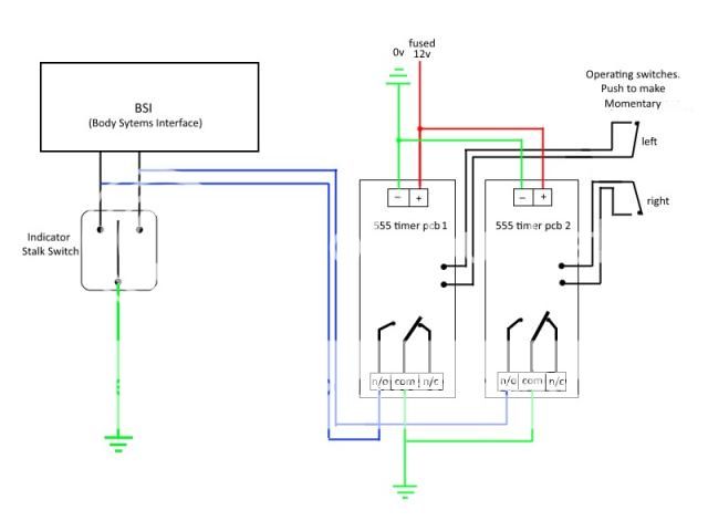
It works absolutely fine utilising two very conveniently located OEM push switches.... one on the end of the wiper stalk for the right and one on the indicator stalk itself for the left. It was not possible to use the stalk itself to trigger the 555's as it upset the two data lines coming from the BSI unit. Normal functioning of the indicators remain unimpaired.

The way these 555 pcb's operates is as follows.
They are powered up permanently. When one or other of the momentary push switches is closed and released, it starts the timing sequence in the 555. The on board SPDT relay changes over and places 0v (vehicle earth) on one or other of the data lines from the BSI. This causes the indicators to blink. After a pre-determined time, 555 chip times out and releases the relay, thus removing 0v from the data line and the indicators stop blinking.

The problem I get is that when I turn on my headlights (55W HID) the ignitor circuit for those arc bulbs seems to be putting a huge spike across the 12v system and both the 555 timer pcb's self trigger.

I think I need some sort of suppression somewhere on the supply line but don't know what/where to put it.

Any ideas?

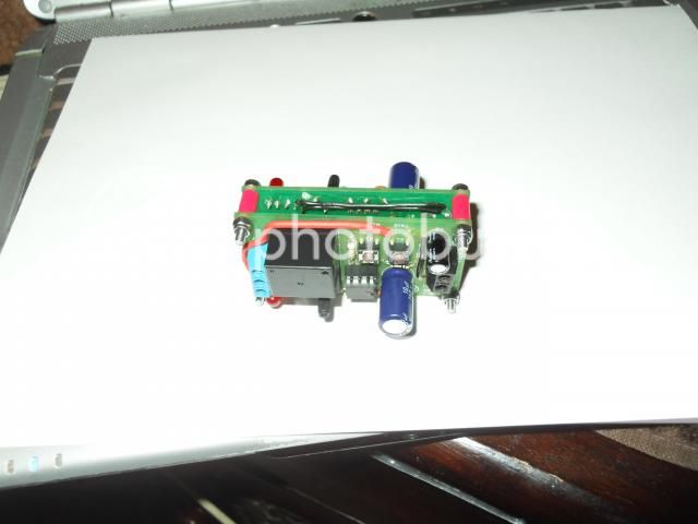
The two 555 pcb's piggy backed together.
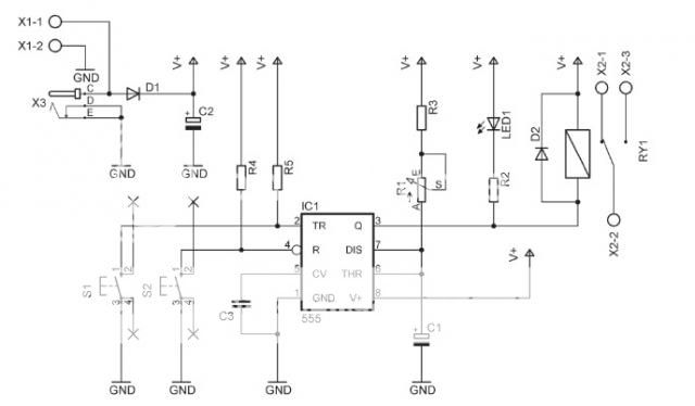
SDC17963_zps2884edb1.jpg


The circuit.
Indicatoronetouch3_zps35f52023.jpg
 
What do you need....a circuit diagram of the 555 pcb's?
These were off the shelf kits from Maplin (in the UK). They didn't come with a circuit diagram as such.
 
Welcome to ETO, mark.w!

Try a large (1000uf, ≈100VDC) electrolytic cap across the 12VDC (the connectors on the PCB(s) will do - the idea is to have them as close to the 555 as is possible).

That should absorb the spike. Also, check that the Reset pin(s) (4) of the 555(s) is connected to Vcc (12 VDC) and the 555 Control Voltage pin(s) (5) has a 0.01mF cap to ground.
 
Last edited:
Thank you very much. That sounds very useful.

I'll get a couple of caps (one for each 555 pcb, I presume?) and try them. While the unit is out of the car, I can check on how those pins on the 555 are handled.
The pcb's are equipped with a couple of push buttons for testing, (trigger & reset), so I would guess that at the very least, pin 4 is held high until the reset button is pressed.

PS
Did you mean 0.01nF??;)
 
Well, one 1000uf might do since both PCBs are in such close proximity to each other.


OOPS. Typo on the pin 5 cap!!:woot:

0.01uf. It's just what I've always used. Although the range suggested for pin 5 is all over the place (1nf up...).
 
Many thanks for your input, much appreciated.
I'll report back once I've added the capacitor.

Impressed with the swiftness of replies on here!
 
Just another thought I had.....
I'm an electrician by trade and I always tie-wrap (zip tie?) my looms together for neatness.
In the diagram I posted above, I now realise this means that the four trigger wires (in black which go to and from the switches) are loomed up alongside the power wires.
Could the problem I'm getting be made worse because of this? I'm thinking of inductive/capacitive cross coupling here.........

Anyway, I suppose it wouldn't hurt to get a bit of separation between them.

Out to pick up a nice big fat capacitor today!
 
...four trigger wires (in black which go to and from the switches) are loomed up alongside the power wires.
Could the problem I'm getting be made worse because of this? I'm thinking of inductive/capacitive cross coupling here............

Could very well be contributing to the problem (if not the problem). Either shield (to chassis ground) the trigger wires or, more easily as you suggest, separate them from the power lines (both hot and ground).
 
Just back in after trying the capacitor method and the separation of trigger wires from power wires.
It made no difference.

In an attempt to narrow down this problem, I fed the 555 pcb's from a 9 v battery so as to completely isolate it from the car's power. It still gets triggered by the HID's. This sort of proves that the transient isn't coming down the power wires.

I then found that if I isolate the two pairs of trigger wires from the pcb, the fault goes away. So the trigger wires appear to be picking up this spike. The trigger wires disappear into the car loom at the steering column as they are part of the car's original loom so would be running alongside other power wires from various systems in there. Based on what you have suggested above, should I try re-wiring the trigger wires in a shielded two core cable with the shield tied down to chassis ground? Any other way of preventing this unwanted noise pick up?

Re the 555 pins.
Pin 4 is connected high via a 10k resistor and is pulled down low by the on board reset switch. (not used for this application)
Pin 5 is connected to ground via a 10nF ceramic capacitor.
I'm guessing this is ok as the circuit works fine apart from this 'interference' glitch.

Thanks for your time in helping me here.
 
You could try a cap (at least 100n) between pin 2 and ground.
 
You could try a cap (at least 100n) between pin 2 and ground.
That might do it, alec. Don't see a cap on 2 (see below - pic from another angle off the maplin site (the one ceramic is, presumably, attached to pin 5):
maplin 555 mono.JPG

mark.w, you first try twisting (their entire length) the trigger wires together and see if that helps. Twisted pairs are more resistance to inductive spikes (noise).
 
Yes, that's the one.
I found a schematic of the 555 circuit that I'm using here if it's any help.
My trigger wires out to the momentary push switch are taken from the two points marked as 'X' from S1 on each board.
555_zpsa7a039ce.jpg


You're right, there's no cap on pin 2, just a 10k pull up resistor......so I'll try adding one on each board. Easy fixes first though, I'll try the twisted pair route to see if it improves things.:)
What about using a shielded twin cable for each pcb's trigger pair if the twisting doesn't help?

It's a damn nuisance as this little mod works very well in all other aspects!


PS I don't know if it's relevant to the problem, but I have changed the original LM555 chip supplied by Maplin to a CMOS version as I needed low quiescent current draw while the system was dormant.

Edited for lousy grammar...
 
Last edited:
If none of the above helps, do you know anyone with an oscilloscope?

The shielded cable route is an option. As you can imagine, your symptoms and a solution are becoming something of a poser, which could be rather easily sussed out with the scope (to observe spikes, if any, caused by the activation of the HIDs), if it comes to that.

I suspect that a simple analog voltmeter (one with an actual dial) might be helpful in lieu of the scope.
 
Sadly, I don't know anyone with a 'scope and to be completely honest, I don't really do enough in the world of electronics to justify owning one outright (although I always have one or two in my watch list, just in case a bargain appears....!).

I do have an Avo 8 analogue meter though which gets used regularly to display a varying current...something that confuses the hell out of digital multimeters. I'm not sure whether it would be capable of capturing this single spike though, even on a sensitive range, due to the nature of it's damped meter movement. Worth a try nevertheless...thanks for the tip.

I will have a chance to trial the twisted pair option today and if that proves unsuccessful, I will try the screened cable instead. If both these options don't cure it, then I'm up against a brick wall with it! :banghead:
I'll have to temporarily disable the circuit and go back to the drawing board for a while and curse the decision not to pursue a career in electronics in my youth.....:)

Thanks again for all the replies. Very much appreciated.
 
Last edited:
If both these options don't cure it, then I'm up against a brick wall with it!
Don't forget the 'cap on pin 2' option.
 
Well, still no go!
Twisted pair for the trigger made no difference, neither did the screened pair. I soldered on a 100nF ceramic on one board between pin 2 & ground to try it and it still picks up the noise. (the capacitor was on the same time as the screened trigger wires btw).
I've exhausted my options now, so for the time being, the circuit has been disabled and normal functions returned to the stalk end buttons.

Would the fact that I replaced the 555 chip with a CMOS version make the trigger line more sensitive, or am I barking up the wrong tree here?
 
OK, I am coming late to the discussion and without actually seeing the equipment, the best suggestion that I can make is to put a simple low pass filter on the inputs as I have indicated in my attached edit to your schematic.

You are already part way there with the 100nF cap, but adding the 1k ohm resistor MAY make all the difference.
Give it a try and see what happens.

JimB

555 Re-Trigger.JPG
 
Thanks for the reply Jim and taking the trouble of adding to the diagram.
As a sparky, I understand what components are meant to do, but can you explain how this R/C filter works. Is it something like getting the unwanted spike to charge up the capacitor instead of finding it's way into the trigger line on pin 2?
I guess if unsuccessful, maybe I could play around with component values a bit?

Not going to be able to progress this till next weekend unfortunately.....
 
Status
Not open for further replies.

Latest threads

Back
Top