Continue to Site

Welcome to our site!

Electro Tech is an online community (with over 170,000 members) who enjoy talking about and building electronic circuits, projects and gadgets. To participate you need to register. Registration is free. Click here to register now.

  • Welcome to our site! Electro Tech is an online community (with over 170,000 members) who enjoy talking about and building electronic circuits, projects and gadgets. To participate you need to register. Registration is free. Click here to register now.

555 problem

Status
Not open for further replies.

mayooya

New Member
hi
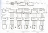
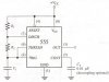
i just wanna ask about something in the 555 timer... i have a school project which is about a digital clock.. i'm attaching a very simplified out line of the circuits.. i'm not attaching the details... anyway the problem is in the 555 timer ...i think it's not working properly so i just wanna know how to check it & to know if it working or not without using the oscilliscope...
i hope u can help me.
:roll:
 
Hello.

I did not see the attachment - could you repost it?

Anyway, my first suggestion is to check the reset input (Pin 4); you may be resetting your timer.

In addition, if you can post all the pin-connections, I'd know if if the wrong thing was connected in the wrong spot.
 
i'm trying to attach them but i can't :roll:
 

Attachments

  • digital_clock.jpg
    digital_clock.jpg
    76.7 KB · Views: 755
  • 555_186.jpg
    555_186.jpg
    19.7 KB · Views: 756
  • 555_211.jpg
    555_211.jpg
    19.7 KB · Views: 765
For the 555 timer, I assume you have R1, R2 and C1 handy. Connect just the 555 timer as shown in your first attachment, and observe the output on the oscilloscope.

The total period of the 555 output is found with this formula:
T = 0.693 x [R(1) + 2R(2)] x C(1)

Calculate your expected period, and compare with your measured period. Doing so should determine if the 555 timer is working as expected.
 
hello!!
i calculated R1 & R2 from this relation before and i'm using 10Kohm & 2.2Kohm resistors and a 100 micro farad capacitor..is there a range or something for these values ???
Is't there any other possible way for checking except the oscilloscope??
I'm using a breadboard by the way.
 
Remember? He doesn't have an oscilloscope!

Let's hope that the value of R1 is small with respect to R2. If not, for now, make the value of R1 1K ohm and the value of R2 somewhere around 47K ohms. The output should then be close to a square wave. If the value of R1 is already small compared to that of R2, leave the circuit as is.

Connect a 150 ohm resistor in series with the anode of a common LED. With your 555 circuit running, ground the cathode (flat side) of the LED and connect the other end of the 150 ohm resistor to the +5v supply and note the LED brightness. Now connect the resistor to the output (pin 3) of the 555. If the 555 is working properly, the LED will still glow, but the brightness should be dimmer.

When folks see a digital clock, they tend to expect some accuracy. By trading out the original 60 Hz source (it was from the line voltage, I'm sure) and the other two counters with the 555, you've seriously affected the accuracy of the clock and you'll be chasing the time all over the place. You'll notice error creeping in each day if not each hour.

The orignal 60 Hz was probably a sample taken fron the secondary of the power transformer. If you're using a wall wart or other power supply, you may not have a secondary from which to tap. So, you're stuck with the 555 at this point. But if you want accuracy without the line frequency sample, then you could make a simple crystal oscillator driving the appropriate counter chain to give you your 1 pps output to drive the seconds counter.

Dean
 
I believe the minimun for R1 is 1k Ohms, and that R1 + R2 should not exceed 6.6 Megaohms. I am not sure about the 555's maximum limitations for a capacitor, but I think using such high capacitors may generate leakage current ... though I doubt it will be a serious problem for your experiment.

(This might seem silly, but did you try connecting the capacitor with the short side to ground? If so, can you switch this?)

I believe the best way to test the output of a timer without the scope is by using an LED (and 100-300 Ohm resistor).


Edit: Sorry Dean, I wrongly assumed he had one; he stated "the oscilloscope" twice, as if one was present but he did just not want to use it; then, his reply to my suggestion did not state "I do not have an oscilliscope to use." I assumed too much, it seems.
 
hey
thanks all for ur help...

P.S:.
------
i don't have an oscilliscope at home.. just at school.
Please stop refering me as he.. i'm a girl.
 
Out of the numerous 555 calculators on the internet, most do not make much sense as they all require me to type in values of R and C which I do not know and am going to find out in the first place.

Eventually I came across one that let me enter the frequency I wanted instead of the component values. I must give my praise to the author as it makes the most sense to me. Clicks the link below. (I'm sorry if I do not post a link to your excellent 555 calculator as I stopped at the first working site as suggested by Google)

**broken link removed**
 
Sorry, Mayooya! In my old-school English, if you don't know the gender or are addressing generic gender, you always use masculine. I never did like the politically-correct and cumbersome "he/she" crap. It makes for terrible public reading!

I never use on-line calculators, computer programs or nomogaphs for such simple things as Ohm's Law or 555 timer calculations. My workbench notebook has the original Signetic equation and two reorgainizations of the same:


f = 1.443/[(Ra+2Rb)C]

Rb = (1.433 - fRaC)/(2fC)

Ra = (1.433 - 2fRbC)/(fC)


1.443 is rounded; a more exact, but never-needed constant here is 1.442695041 -- merely trivial information that I have written down.


Since a simple rectangular waveform is the norm and I usually don't need a true square wave, I find it easiest to simply always use 1K ohm for Ra (R1 in this thread's diagrams) since it is the lowest value allowed in the 555 specs and then work the other two values from that, keeping Rb within the allowable specs. I don't like getting a lot above 1M ohm for Rb and I don't like using electrolytics for C if I can help it. If I have to have a large C, I try to use a tantalum cap for lower leakage.

Now, if you need a custom pulse width and frequency, then you're going to have to diddle with the value of Ra, of course.

Dean
 
Dean Huster said:
1.443 is rounded; a more exact, but never-needed constant here is 1.442695041 -- merely trivial information that I have written down.

And if you round it again, you'll get 1.433.
 
Hi Zach,
Mayooya called herself Birdie on the other site that she posted this same problem. It's fun switching from one site to the other to see the difference in the information she provides, and the different answers she gets.
On the other site she wasn't called a guy. In one of her profiles she is an exotic Egyptian girl! :lol: :lol:
 
Status
Not open for further replies.

Latest threads

New Articles From Microcontroller Tips

Back
Top