wejos
Member
hi guys,
is it possible to breakdown a decimal value e.g. 123 through code and assign the individual numbers to GPR. something like: in address 0x0C, the value 1 is stored; in address 0x1C, the value 2 is stored; and in address 0x0D, the value 3 is stored. this way this will really really spare me a lot of space.
what iv'e done is i hard coded the value and this went on to 255 of this routine:
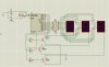
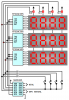
if my math is correct i have to use 3-4 16f84 chips. but if you can split VALIN to 3 decimal values, only two is needed to drive a 7-seg display (X3).
i guess i ran out of space because i get this error "0566 not between 0000 and 03FF". so more PIC is needed and if there is a way to split decimal, boy that'd really save my day : )
thanks in advance
is it possible to breakdown a decimal value e.g. 123 through code and assign the individual numbers to GPR. something like: in address 0x0C, the value 1 is stored; in address 0x1C, the value 2 is stored; and in address 0x0D, the value 3 is stored. this way this will really really spare me a lot of space.
what iv'e done is i hard coded the value and this went on to 255 of this routine:
Code:
MOVF  VALIN,W
	   XORLW 0x00
	   btfsc STATUS, Z
       GOTO  WR0
       GOTO  WR1X
WR0    MOVLW 0x00
       MOVWF VALF
       MOVLW 0x00
       MOVWF VALS
       MOVLW 0x00
       MOVWF VALT


WR1X   MOVF  VALIN,W
	   XORLW 0x01
	   btfsc STATUS, Z
       GOTO  WR1
       GOTO  WR2X
WR1    MOVLW 0x01
       MOVWF VALF
       MOVLW 0x00
       MOVWF VALS
       MOVLW 0x00
       MOVWF VALT


WR2X   MOVF  VALIN,W
	   XORLW 0x02
	   btfsc STATUS, Z
       GOTO  WR2
       GOTO  WR3X
WR2    MOVLW 0x02
       MOVWF VALF
       MOVLW 0x00
       MOVWF VALS
       MOVLW 0x00
       MOVWF VALT
if my math is correct i have to use 3-4 16f84 chips. but if you can split VALIN to 3 decimal values, only two is needed to drive a 7-seg display (X3).
i guess i ran out of space because i get this error "0566 not between 0000 and 03FF". so more PIC is needed and if there is a way to split decimal, boy that'd really save my day : )
thanks in advance
Last edited:
 it's 3,000+ line of code but you will not believe i actually typed all the 255 of them. i understand it will work but won't be cost effective and because there is much simpler way to accomplish this, there is no point really to head that direction