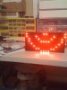
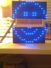
I have been working a few weeks on a large RGB LED sign project using a Parallax SX28 micro-controller chip. I can get basic data (smiley face) to display fine in either Red, Green or Blue LEDs on two smaller LED 16x8 RGB modules that are cascaded and will eventually be further cascaded a few dozen times to form a large "Full Color" outdoor sign in what is suposed to work in 24 - 36 bit color according to the datasheet.
I have been using Parallax micro-controllers like the Basic Stamp 2 and SX chips for over 3 years now in their PBASIC and SXB which are both B.A.S.I.C. language variants. The SX micro-controller has far more capabilities than the Basic Stamp 2 so that is what I have been developing my sign with. However, I am now at a point where I need PWM to get 256 shades of Red, Green and Blue LEDs to get the "Full Color" 24 or 36 bit display. Eventually I will need to find a way to add in video to the PWM to complete this project. But for today, I am having a very hard time finding a way to do PWM that apparently can be done on this type of a display but not as easy if at all on a Parallax SX chip. I also beleive when I move onto animation, the Parallax SX chip won't have enough internal RAM to support this project either.
So I am looking at moving to either a PIC or AVR or some other recommendation to complete this project. I have never worked with either of these micro-controllers and would start from scratch with only my Parallax SX chip background and experience to guide me.
Can someone tell me of a robust micro-controller that can handle a project like this? The RGB LED sign is comprised of cascading modules that are SPI based very similar to chips like the 74HC595. I can provide all data upon request to this project. The only inputs I have to the sign modules (which are RGB 16x8) are the following: R1A, R2A, R1B, R2B, G1, G2, B1, B2, CLOCK, LATCH, /OE and Ground. These signals are on a connector jack with input and output to the next modules. The 1 and 2 for the RGB just refer to 2 data streams (upper and lower halves of the modules for 64 bits per data stream).
I need to work in a BASIC language as I don't know C nor really want to learn Assembler. It needs to have an easy PWM module or format to implement for this SPI based sign. USB or Serial capability to a PC to eventually receive video RGB data would be needed. Plenty of RAM to handle RGB video formats of sign display data, arrays, etc.. is needed.
What are my options here - or what are other RGB sign manufacturers doing?