Here is a simple demo using a graphic LCD on Bill's Unicorn.
My C is a little rusty and the C18 compiler with the Harvard architecture makes it a little more challenging. I did however manage a few routines that should get people started.
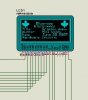
This is what it looks like when it's working,
**broken link removed**
As you can see, I'm not an artist and my version of the Canadian Maple leaf leaves a lot to be desired.
This should work with any pic18 and a GLCD with two KS0108 controllers. It is however a lot simpler with the Unicorn.
The attached zip file contains the c files. Comments and constructive criticism welcome. Thinking about it, the lack of comments in the code will probably be most commented on.
Mike.
My C is a little rusty and the C18 compiler with the Harvard architecture makes it a little more challenging. I did however manage a few routines that should get people started.
This is what it looks like when it's working,
**broken link removed**
As you can see, I'm not an artist and my version of the Canadian Maple leaf leaves a lot to be desired.
This should work with any pic18 and a GLCD with two KS0108 controllers. It is however a lot simpler with the Unicorn.
The attached zip file contains the c files. Comments and constructive criticism welcome. Thinking about it, the lack of comments in the code will probably be most commented on.
Mike.
Last edited: